Two-Dimensional Photonic Crystal Cavity and Channel Add/Drop Filter

a photonic crystal and cavity technology, applied in the field of cavities and channel add/drop filters, can solve the problems of inability to alter the cavity structure by using this technique, the q factor is large, and the cavity is totally inadequate, and achieves the effect of high wavelength resolution

Active Publication Date: 2007-04-19
PRESIDENT +1
View PDF0 Cites 4 Cited by
  • Summary
  • Abstract
  • Description
  • Claims
  • Application Information

AI Technical Summary

Benefits of technology

[0033] A principal object of the present invention, in view of the situation with the conventional technology, is to afford a high-Q cavity within a 2D photonic crystal, and furthermore to combine such a cavity with a waveguide to make available a channel add / drop filter having high wavelength resolution.

Problems solved by technology

This means that with a cavity such as disclosed in Unexamined Pat. App. Pub. No. 2001-272555, the largeness of the Q factor is insufficient, and with the 3-nm FWHM, the cavity is totally inadequate for separating from one another multi-channel signals whose peak-wavelength spacing is approximately 0.8 nm.
Yet a guide to approaching where and in what way is best to alter the cavity structure cannot by obtained from this technique.
In other words, the result of trial and error is for the most part fortuitous; moreover, a cavity having a high Q value can only be obtained by altering the geometry of extraordinarily many air holes.
The paper notes that devices utilizing acceptor-type defects do not achieve Q high enough to provide the filtering resolution required for WDM applications, and that meanwhile researchers have concentrated efforts on improving the Q of defect cavities alone (rather than the Q of the cavity-waveguide system as a whole, functioning as a filter).
Moreover, the methodology utilized by Srinivasan and Painter is inapplicable to an L3 defect according to Akahane et al., in the first place because the defect-constituting holes are filled; the defect is constituted simply by a run of missing holes, not by altering the size of a hole on a single point or of a twinned pair about a single point.

Method used


Image

  • Two-Dimensional Photonic Crystal Cavity and Channel Add/Drop Filter
  • Two-Dimensional Photonic Crystal Cavity and Channel Add/Drop Filter
  • Two-Dimensional Photonic Crystal Cavity and Channel Add/Drop Filter

Examples


Embodiment Construction

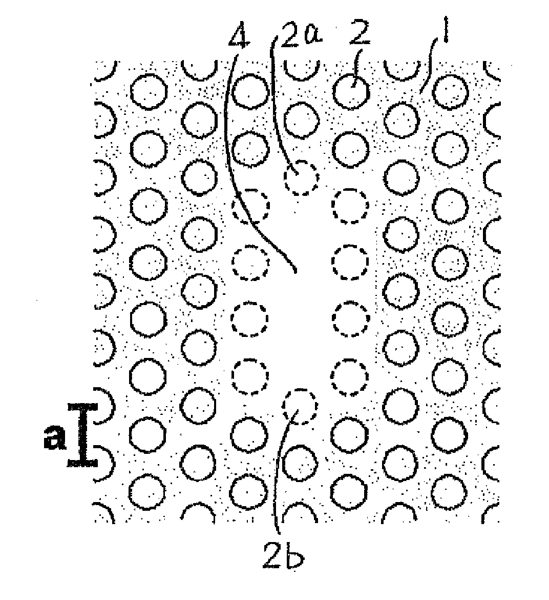
[0068] Initially the present inventors looked into the characteristics, within a 2D photonic crystal, not of a cavity consisting of an acceptor-type defect as in FIG. 10, but of a cavity consisting of a donor-type point defect. As described earlier, donor-type defects contain one or more lattice points, and through-holes are missing in those lattice points.

[0069] What has chiefly been studied to date are point defects containing only a single lattice point, from the perspectives that owing to their structural simplicity they are easily analyzed electromagnetically and that they are of minimal size. This has meant that with donor types as well, point defects that contain a plurality of lattice points have not to date been studied extensively. Given the circumstances, then, the present inventors investigated the characteristics of donor-type point defects that contain a plurality of lattice points.

[0070]FIG. 11 is a schematic plan view representing a portion of a 2D photonic crystal...


PUM


Abstract

In 2D photonic crystals, cavities having a heightened Q factor are made available, wherein combining the high Q cavities with waveguides affords channel add/drop filters having high resolution. In a cavity constituted by a point defect within a 2D photonic crystal, the 2D photonic crystal is configured by an arrangement, in a two-dimensional lattice of points defined in a slab (1), of low-refractive-index substances (2) having a low refractive index relative to the slab (1) and being of identical dimension and shape. The point defect (4) contains a plurality of three or more lattice points that neighbor one another, and in these lattice points no low-refractive-index substances (2) are arranged; therein the dimension of the low-refractive-index substance (2) that should be arranged to correspond to at least one of the lattice points nearest the point defect (4) is dimensionally altered from a predetermined dimension.

Description

BACKGROUND OF THE INVENTION [0001] 1. Technical Field [0002] The present invention relates to cavities and channel add / drop filters employing photonic crystals (PCs), and in particular to improvements in the characteristics of cavities and channel add / drop filters based on two-dimensional photonic crystals. [0003] 2. Description of the Related Art [0004] It should be understood that in the present specification, the significance of the term “light” is meant to also include electromagnetic waves that relative to visible light are of longer as well as shorter wavelength. [0005] Along with advances in wavelength division multiplexed (WDM) optical communication systems in recent years, the importance of ultrasmall add / drop filters and channel filters in which enlarged capacity is being targeted is on the rise. In this area, then, attempts are being made to develop extraordinarily small-scale optical add / drop filters by employing photonic crystals. In particular, with photonic crystals n...

Claims


Application Information

Patent Timeline
Patent Type & Authority Applications(United States)
IPC IPC(8): G02B6/02G02B6/032G02B6/12G02B6/122G02B6/34
CPCB82Y20/00G02B6/1225G02B6/12
Inventor NODA, SUSUMUASANO, TAKASHIAKAHANE, YOSHIHIRO
Owner PRESIDENT
Why Eureka
Try Eureka