
Intravenous catheter introducing device with a tubular outlet member

Inactive Publication Date: 2007-04-19
SHUE MING JENG +2
View PDF8 Cites 56 Cited by
  • Summary
  • Abstract
  • Description
  • Claims
  • Application Information

AI Technical Summary

Benefits of technology

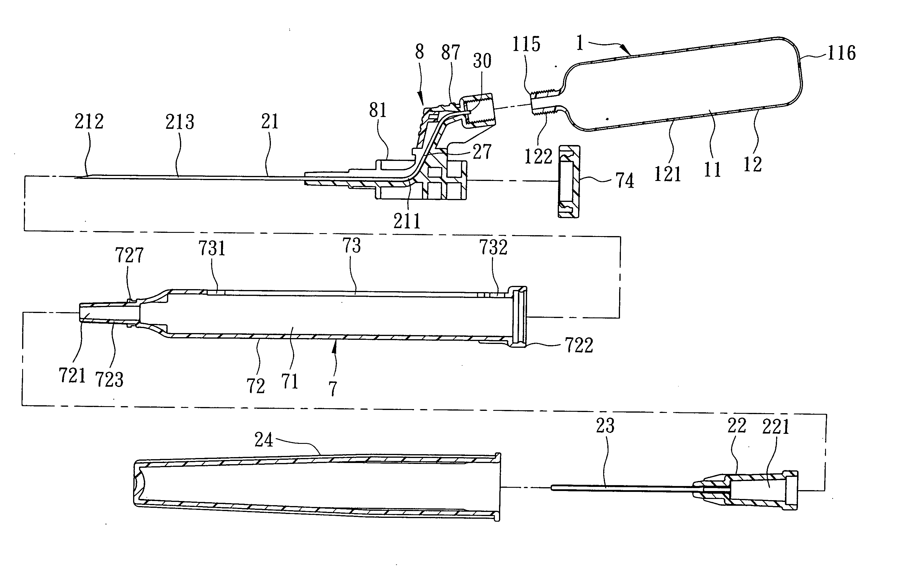
[0008] The object of the present invention is to provide an intravenous catheter introducing device which has a tubular outlet member that is in fluid communication with a needle cannula and that is disposed outwardly of a barrel so as to be connected to a flashback member for facilitating the catheter introducing operation.
[0009] Another object of the present invention is to provide an intravenous catheter introducing device which ensures retraction of a needle cannula into a barrel after use.

Problems solved by technology

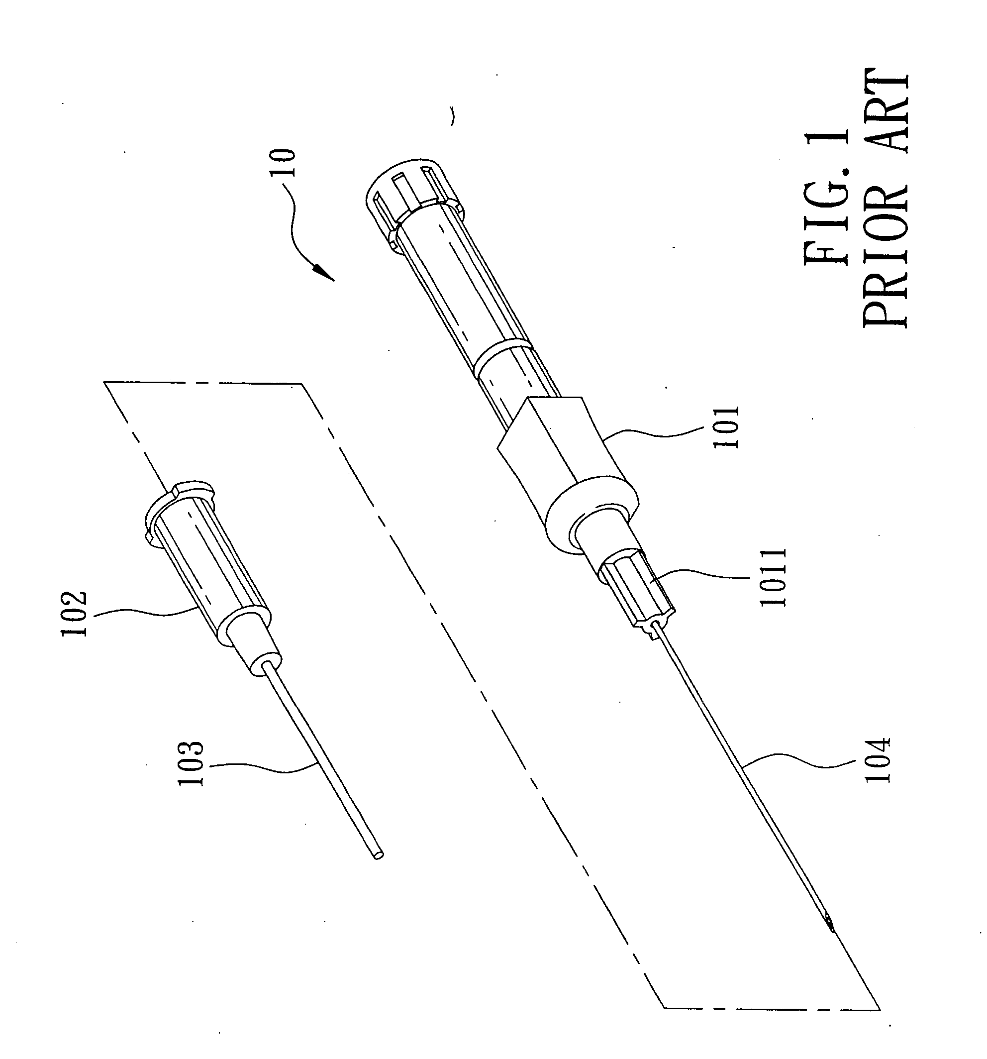
Moreover, blood contamination may occur during connection of the catheter hub 103 to the transfusion member or the empty barrel.
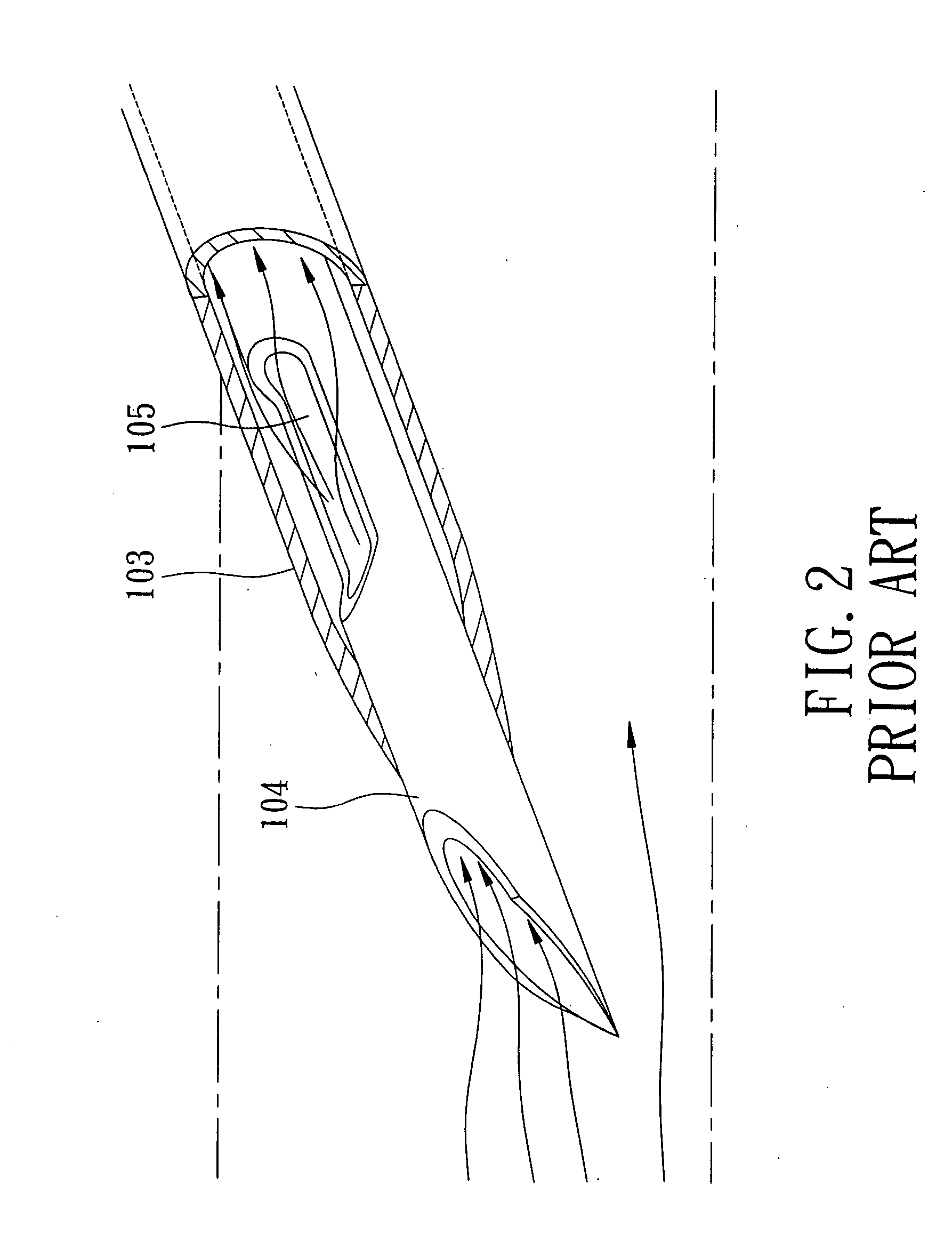
Moreover, the conventional intravenous catheter inserting device 10 is specifically not suitable for patients whose blood pressure is not sufficient to permit flow of blood through the notch 105, such as an emergency case, aged people, and pediatrics patients, and patients whose target vein is barely visible due to abundant adipose tissue, such as women and obese patients, since the health care worker will have difficulty determining whether the catheter 103 has been successfully introduced into the target vein, and may need to locate the vein by moving the needle cannula 104 in the skin of the patient, thereby complicating and prolonging the cannulation procedure and causing great discomfort to the patient.

Method used


Image

  • Intravenous catheter introducing device with a tubular outlet member
  • Intravenous catheter introducing device with a tubular outlet member
  • Intravenous catheter introducing device with a tubular outlet member

Examples


second embodiment

[0082] Referring to FIG. 9, the second preferred embodiment of an intravenous catheter introducing device according to this invention is shown to be similar to the first preferred embodiment in construction. In the second embodiment, a biasing spring 83 is received in the guiding groove 71, and has a front spring end 831 which is secured to the force effecting end 81, and a rear spring end 832 which is secured to the tail end portion 722. Alternatively, the rear spring end 832 can be secured to the end cap 74, as shown in FIG. 33. Thus, the biasing spring 83 is tensioned by the needle retracting member 8 when the needle retracting member 8 is in the position of use. In addition, an inner surface of the barrel wall 72 is formed with an annular rib 728 which can reinforce the retention of the needle retracting member 8 in the position of use.

[0083] Therefore, referring to FIGS. 11 and 12, when the user actuates the shifter 87 with the hand that grips the barrel wall 72 to disengage fr...

third embodiment

[0084] Referring to FIG. 13, the third preferred embodiment of an intravenous catheter introducing device according to this invention is shown to be similar to the second preferred embodiment in construction. In the third embodiment, a gripped member 75 is attached to the barrel wall 72 in the vicinity of the front retaining region 731, and is configured to be held by a user's thumb for moving the shifter 87. A triggering member 84 is pivotally mounted on the barrel wall 72 at a fulcrum point, and has a weight end 841 which is disposed to releasably hold the shifter 87 when the needle retracting member 8 is in the position of use, and a power end 842 which is disposed at an opposite side of the weight end 841 relative to the fulcrum point so as to be actuated to permit the weight end 841 to disengage from the shifter 87, thereby enabling the needle retracting member 8 to move to the disposal position. Thus, after the tubular catheter 23 is introduced into the patient's vein, the use...

fourth embodiment

[0085] Referring to FIG. 14, the fourth preferred embodiment of an intravenous catheter introducing device according to this invention is shown to be similar to the second preferred embodiment in construction. In the fourth embodiment, the front retaining region 731 extends in a circumferential direction that surrounds the axis (X). In addition, the bracing member 82 has a barrier rib 823 which can be inserted into the front retaining region 731 to guard the shifter 87 against an undesired disengagement from the front retaining region 731. In use, the bracing member 82 is detached from the barrel 7 first, and the catheter introducing operation is subsequently conducted.


PUM


Abstract

An intravenous catheter introducing device includes a needle cannula with a rear connecting end that is forced by a needle retracting member to displace relative to a barrel between a position of use to permit a needle tip to pierce a patient's vein, and a disposal position to permit retraction of the needle tip into the barrel. A tubular outlet member is disposed downstream of the rear connecting end, and is mounted radially and outwardly of the barrel. A flashback member can be connected to and in fluid communication with the tubular outlet member so as to permit the user to check whether a tubular catheter has been successfully introduced into a target vein of the patient. In addition, the flashback member can provide a blood drawing function to facilitate flow of blood into the flashback member.

Description

CROSS-REFERENCE TO RELATED APPLICATION [0001] This application claims priority of Taiwanese Application No. 094125240, filed on Jul. 26, 2005. BACKGROUND OF THE INVENTION [0002] 1. Field of the Invention [0003] This invention relates to an intravenous catheter introducing device, more particularly to an intravenous catheter introducing device which has a tubular outlet member that is in fluid communication with a needle cannula and that is disposed outwardly of a barrel so as to be connected to a flashback member for facilitating the catheter introducing operation. [0004] 2. Description of the Related Art [0005] Intravenous catheter inserting devices are generally used to administer medication fluids into or draw blood from a patient's vein. Referring to FIGS. 1 and 2, a conventional intravenous catheter inserting device 10 is shown to include a tubular needle seat 1011, with a hub end 1011, a needle cannula 104 secured to the hub end 1011, a catheter hub 102 sleeved on the needle s...

Claims


Application Information

Patent Timeline
IPC IPC(8): A61M5/178
CPCA61M25/0693
Inventor SHUE, MING-JENGSHUE, PHILLIPHUANG, DEBORAH
Owner SHUE MING JENG
Learn More