Mutual Monitoring System, Mutual Monitoring Apparatus, Mutual Monitoring Method and Program

Inactive Publication Date: 2007-04-19
NEC CORP
View PDF3 Cites 6 Cited by
  • Summary
  • Abstract
  • Description
  • Claims
  • Application Information

AI Technical Summary

Benefits of technology

[0009] According to the present invention, each mutual monitoring apparatus in the mutual monitoring system can monitor whether or not trouble has occurred in another mutual monitoring apparatus with a small memory size even if there are a large number of mutual monitoring apparatuses to be monitored in the mutual monitoring system. A new mutual monitoring apparatus can easily be added to the mutual monitoring system.
[0010] The reason for this is that each mutual monitoring apparatus retains only information about a monitoring object apparatus and information about a monitor apparatus. Namely, since only information about two apparatuses is retained, the memory size can be reduced as compared to the related art in which identifiers of all mutual monitoring apparatuses to be monitored should be retained. The number of other monitoring apparatuses for which information should be changed when a new monitoring apparatus to be monitored is added to the mutual monitoring system can be also reduced.

Problems solved by technology

This related art has a problem of increasing the load on a network because it is necessary to send a packet by broadcast or multicast.
Further, this related art has a problem of requiring a large memory size for the component information storing portion if there are a large number of computers to be monitored.
It is also not easy to add a new computer to be monitored.
If no response is given from the first computer, it is determined that trouble has occurred in the first computer.
This related art has a problem of requiring a large memory size when there area large number of computers to be monitored.
It is also not easy to add a new computer to be monitored.

Method used


Image

  • Mutual Monitoring System, Mutual Monitoring Apparatus, Mutual Monitoring Method and Program
  • Mutual Monitoring System, Mutual Monitoring Apparatus, Mutual Monitoring Method and Program
  • Mutual Monitoring System, Mutual Monitoring Apparatus, Mutual Monitoring Method and Program

Examples


Embodiment Construction

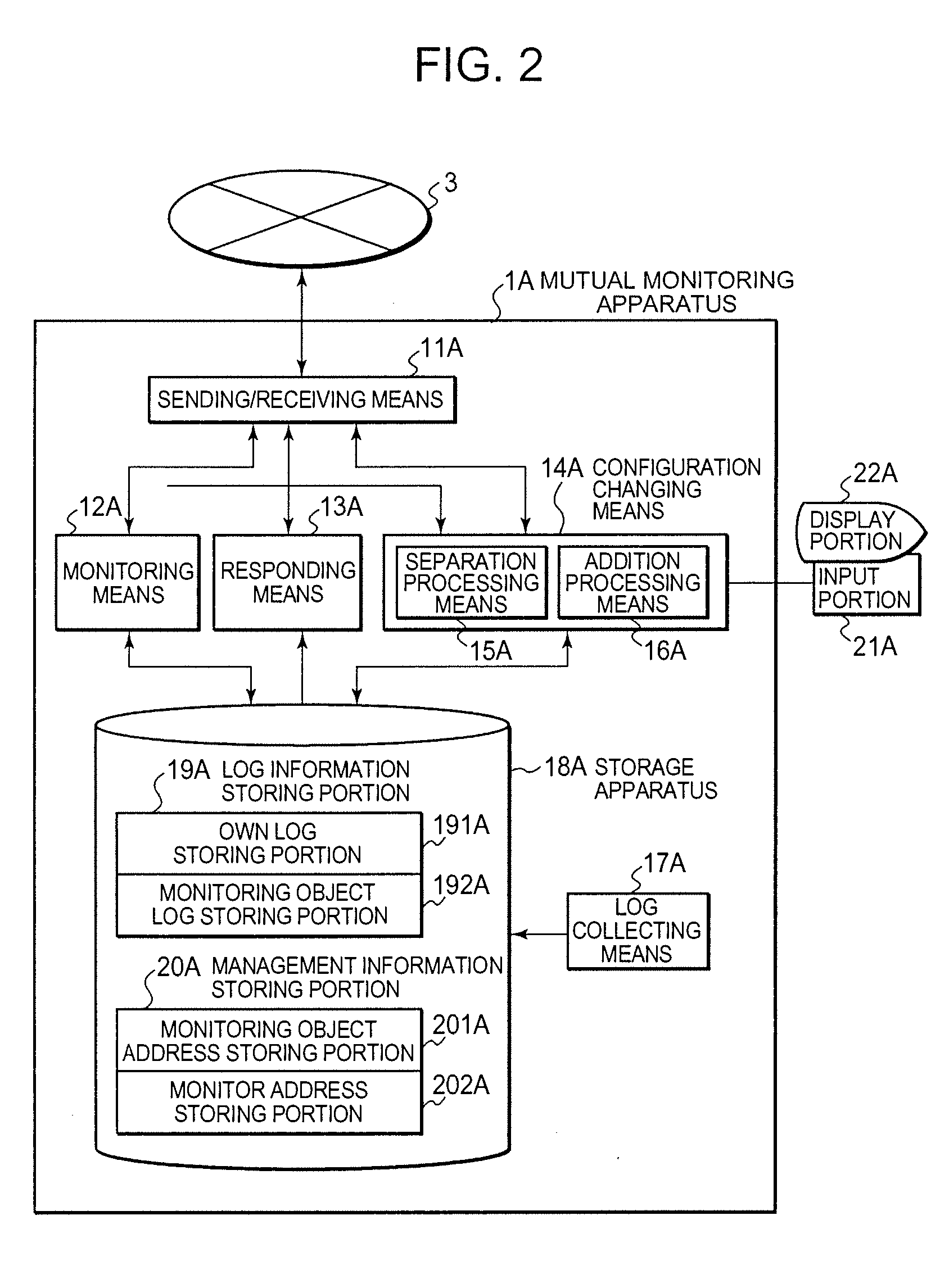
[0042] An embodiment of the present invention will be described in detail below with reference to the drawings. In the explanations described below, subscripts B, C, D, . . . are added when means and the like in the apparatuses 1B, 1C, 1D, . . . are shown. For example, when monitoring means belonging to the apparatus 1C is shown, it is described as monitoring means 12C.

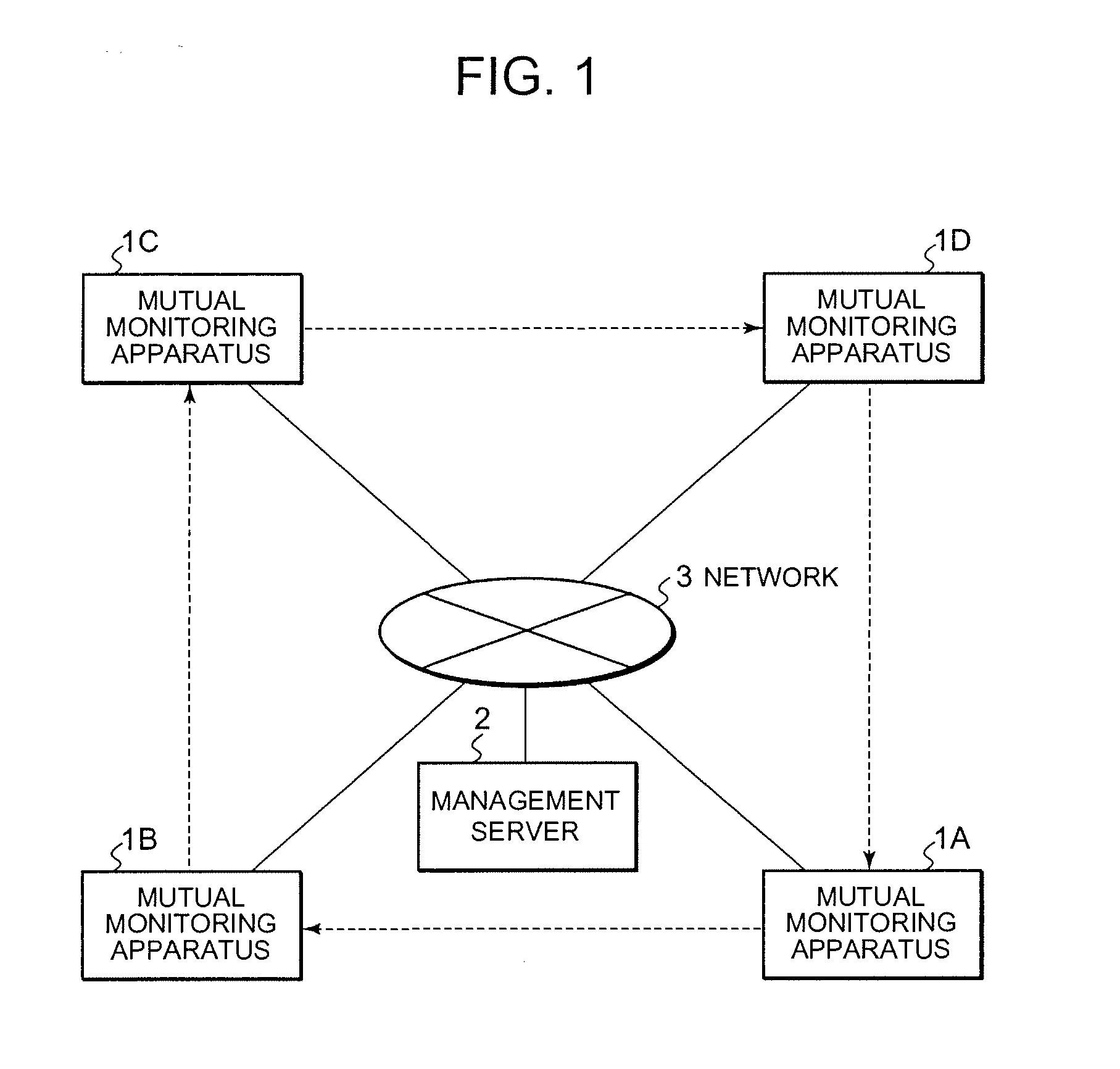
[0043]FIG. 1 is a block diagram showing an example of the configuration of an embodiment of a mutual monitoring system according to the present invention. In the example of the configuration, the mutual monitoring system is comprised of a plurality of mutual monitoring apparatuses 1A to 1D, each of which is an apparatus such as computers connected to a network, a management server 2, and a network 3 for connecting those apparatuses. In this embodiment, mutual monitoring apparatuses 1A, 1B, 1C and 1D monitor mutual monitoring apparatuses(from hereon in the detailed description of the invention simply referred as appar...


PUM


Abstract

A system includes a plurality of apparatuses connected to a network, wherein each apparatus monitors the occurrence of trouble in a monitoring object apparatus which is one of the apparatuses in the system. Further, each apparatus is monitored for the occurrence of trouble in the apparatus by a monitor apparatus which is another one of the apparatuses in the system. The system enables adding and subtracting apparatuses to the system, as well as restoring apparatuses which were previously subtracted due to detected troubles which have been corrected.

Description

BACKGROUND OF THE INVENTION [0001] 1. Field of the Invention [0002] The present invention relates to a monitoring technology for monitoring whether or not trouble has occurred in an apparatus connected to a network, such as a computer, a telephone exchange system or a process controller. Particularly, the present invention relates to a mutual monitoring technology in which an apparatus connected to a network monitors whether or not trouble has occurred in another apparatus connected to the network. [0003] 2. Description of the Related Art [0004] Technologies in which an apparatus connected to a network monitors another apparatus connected to a network include the following technologies. [0005] In the related art described in Japanese Patent Published Application No. 2001-75837, each computer to be monitored regularly sends to other computers a packet including its identifier. The packet is sent by broadcast or multicast. Each computer contains a component information storing portion...

Claims


Application Information

Patent Timeline
IPC IPC(8): G06F17/30G06F7/00
CPCG06F11/3476H04L43/065
Inventor KITAMURA, TOSHIKAZU
Owner NEC CORP
Why Eureka
Try Eureka