Plasma actuator

a technology of actuators and plasma, applied in the direction of positive displacement liquid engines, air-flow influencers, machines/engines, etc., can solve the problem of fluid flow away from the actuator

Inactive Publication Date: 2007-04-26
UNIV OF KENTUCKY RES FOUND
View PDF35 Cites 66 Cited by
  • Summary
  • Abstract
  • Description
  • Claims
  • Application Information

AI Technical Summary

Problems solved by technology

Application of the voltage to the first conductor may result in a fluid flow away from the actuator.

Method used


Image

  • Plasma actuator
  • Plasma actuator
  • Plasma actuator

Examples


example

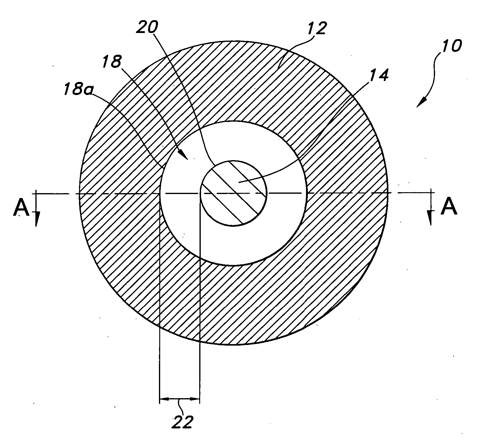
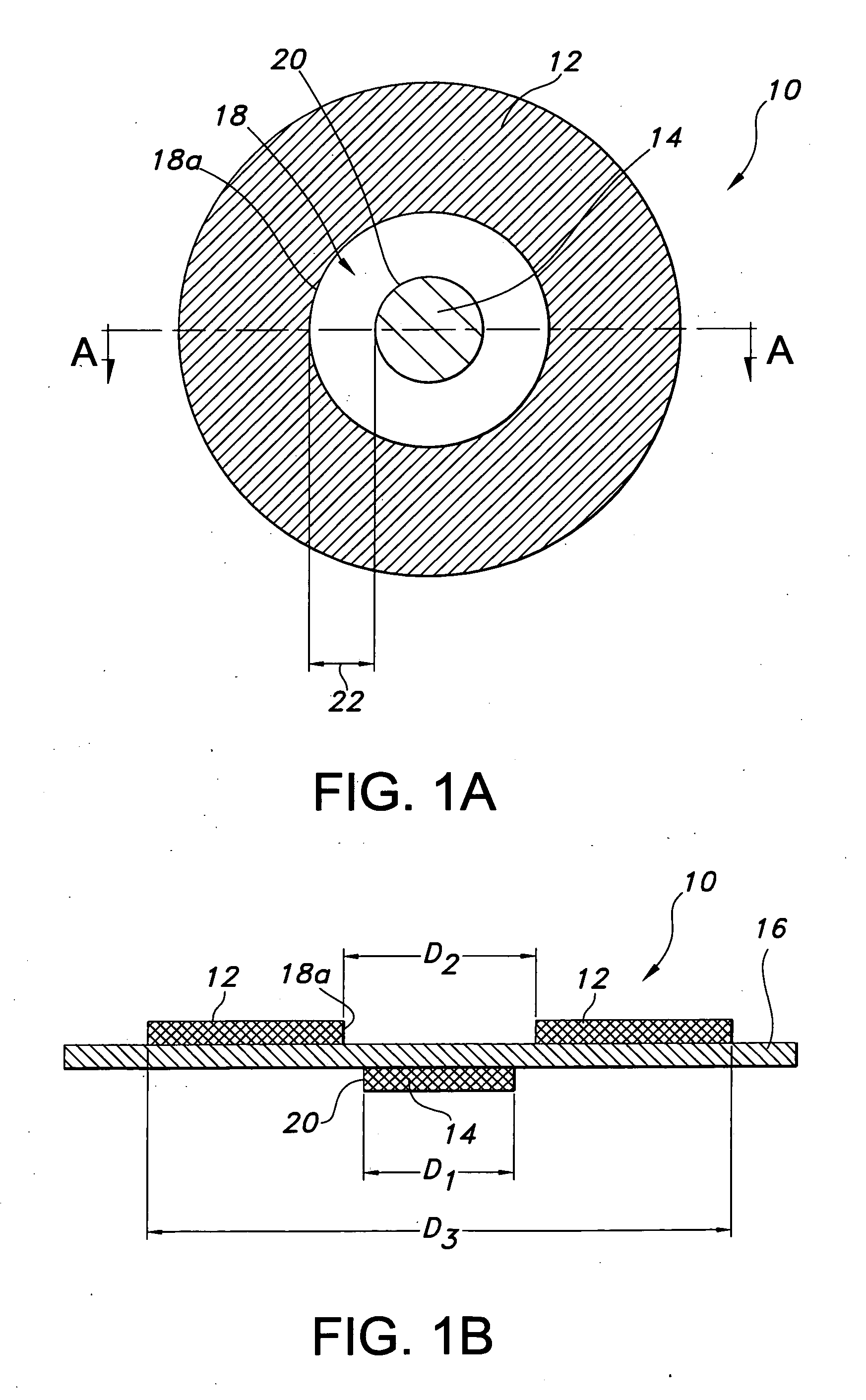
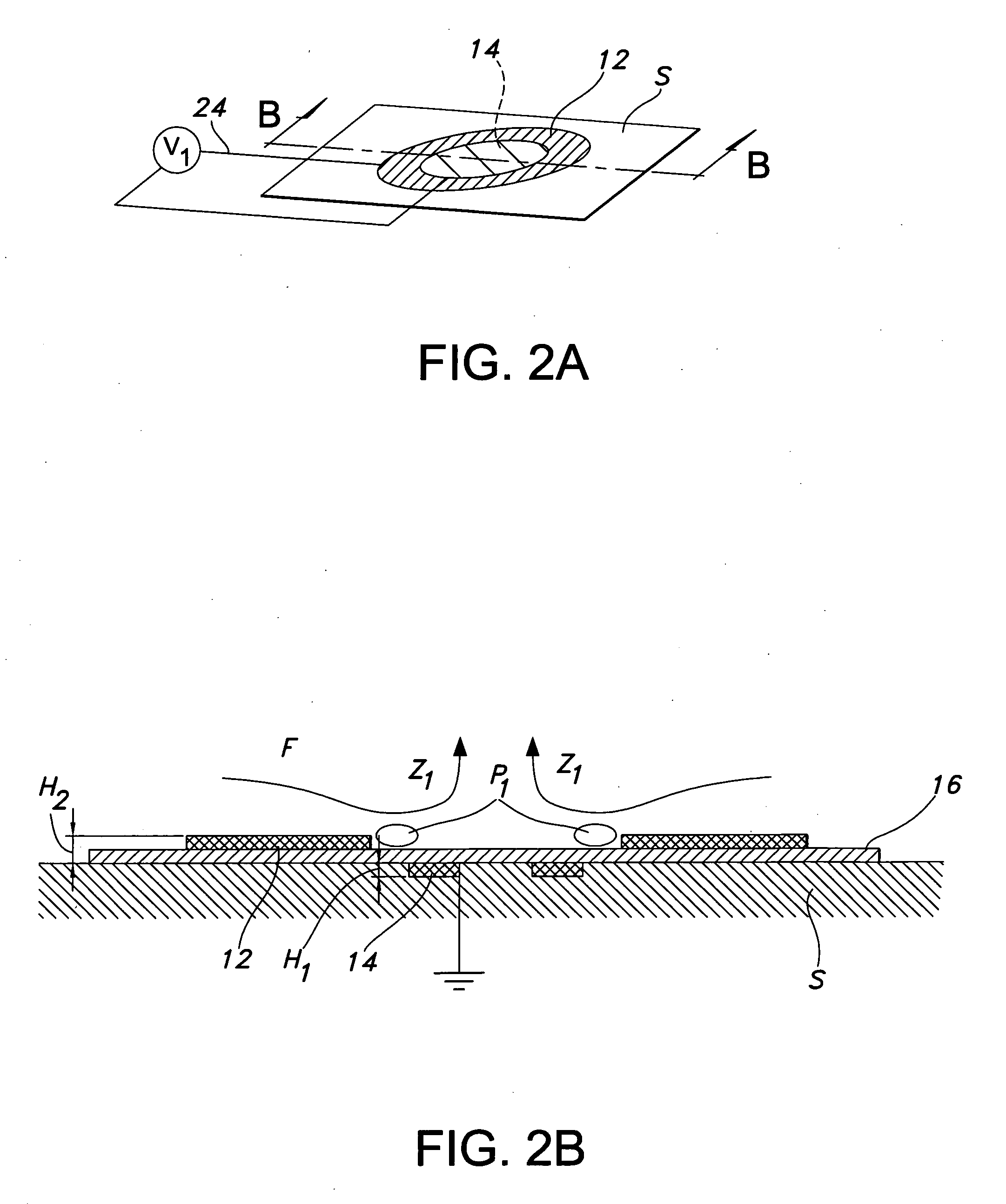
[0037] Plasma actuators were created using a conductive copper tape material. One actuator was created in the form of an array of annular actuators, while the other was created in a linear fashion. A 0.025″ thick alumina ceramic slab was used as the dielectric for a quiescent flow and flat plate boundary layer experiment, while KAPTON was used as the dielectric for a cylinder flow measurement.

[0038] The diameters of exposed and embedded conductors of the annular plasma synthetic jet actuator (“PSJA”) tested were 1″ and 0.5″ respectively, with either no gap or a 0.04″-0.08″ overlap. The dimensions of the linear synthetic jet actuator (“L-PSJA”) used in both quiescent flow and flat plate experiments were chosen to match the PSJA, and the width of the exposed conductors and embedded conductor of the L-PSJA were 0.25″ and 0.5″ respectively, with no gap and a spanwise length of around 3.5″. For quiescent flow measurements on the linear actuator, the width of the exposed and embedded con...


PUM


Abstract

An actuator including a first and second conductor on a dielectric, wherein application of a voltage to the first conductor creates a plasma, thereby modifying a fluid flow in communication with the actuator. Related systems and methods are also provided.

Description

[0001] This application claims the benefit of U.S. Provisional Patent Application No. 60 / 727,364 filed Oct. 17, 2005, the disclosure of which is herein incorporated by reference.TECHNICAL FIELD [0002] The present invention relates to a fluid actuator and, more particularly, to a plasma actuator for manipulating, controlling and / or modifying a fluid flow. BACKGROUND OF THE INVENTION [0003] The ability to manipulate, control, and / or modify (collectively, “modify”) a fluid flow is important for increasing the performance of, or otherwise altering, a fluid system. Some previous attempts to modify fluid flows have focused on passive flow controls (i.e., where an input of external energy is not required). Some of the known passive controls include boundary layer trips, roughness elements, ejector nozzles, and surface perturbations. These passive controls often create turbulence or disruption in the fluid flow. Since these passive methods do not include any form of external energy input, t...

Claims


Application Information

Patent Timeline
Patent Type & Authority Applications(United States)
IPC IPC(8): F15C1/04
CPCB64C23/005F05D2270/172F15D1/12Y02T50/166B64C2230/12Y10T137/2196Y10T137/2191Y02T50/10H05H1/2439
Inventor JACOB, JAMEY D.
Owner UNIV OF KENTUCKY RES FOUND
Why Eureka
Try Eureka