Position detection apparatus using area image sensor

a technology of area image sensor and detection apparatus, which is applied in the direction of instruments, computing, electric digital data processing, etc., can solve the problems of inability to use fingers or the like to carry out input operations, display becomes dark, detection plane is broken, etc., to achieve the effect of improving detection accuracy, and reducing the number of assembly steps

Active Publication Date: 2007-04-26
MINATO ADVANCED TECH INC +1
View PDF44 Cites 83 Cited by
  • Summary
  • Abstract
  • Description
  • Claims
  • Application Information

AI Technical Summary

Benefits of technology

[0028] With use of the above-described means, the following functions can be acquired. That is, it will be needless to execute the adjustment of setting positions of the imaging sections, and instead thereof, the same effect can be achieved by only selecting particular pixels of the area image sensor. Accordingly, as the functions, the number of the assembly steps can be reduced and the quality of the maintenance will be improved. Hence, even though the imaging sections are attached in the inclined state, the position detection apparatus can work by selecting pixels obliquely arraying with respect to the pixel array in the area image sensor. Furthermore, since it is permitted to select a portion that is not straight but is inflected, even when the detect...

Problems solved by technology

For such a manner of detection, a dedicated pointing device that irradiates electromagnetic wave is required, and it is not possible to use fingers or the like for carrying out input operations.
With the position detection apparatus of the pressure-sensitive type, however, there is such a problem that the detection plane is broken when a pointing device of which tip being edged is used.
Further, when such a position detection apparatus is used in combination with a display device so that they are applied for a so-called touch-panel display apparatus, there is such a problem that the display becomes dark in the appearance an the like since a displayed surface must be viewed through the resistive film and the like.
However, in case of the optical position detection apparatus, it has been so difficult to perform the position adjustment of the imaging section to be used for the apparatus.
That is, since the linear image sensor is a sensor being structured in one line, it has been difficult to adjust the field of view of the imaging section structured in one line so as to be parallel alongside of the detection plane and to a position being closer to the detection plane.
As described above, with the optical position detection apparatuses, it was so difficult to adjust the setting position of the imaging section.
Even though a mechanism that can adjust the height and inclination by means of screws is provided, it is difficult for amateurs to accurately adjust the field of view of the imaging section so as to be parallel to the detection plane.
Besides, even though the accurate adjustment has been made at the time of product delivery, the position ...

Method used


Image

  • Position detection apparatus using area image sensor
  • Position detection apparatus using area image sensor
  • Position detection apparatus using area image sensor

Examples


Embodiment Construction

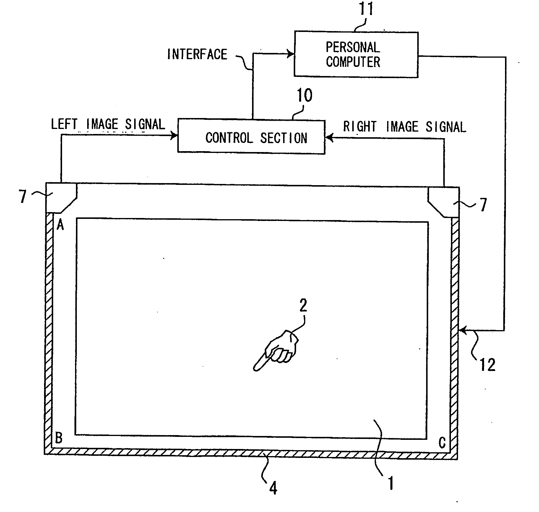
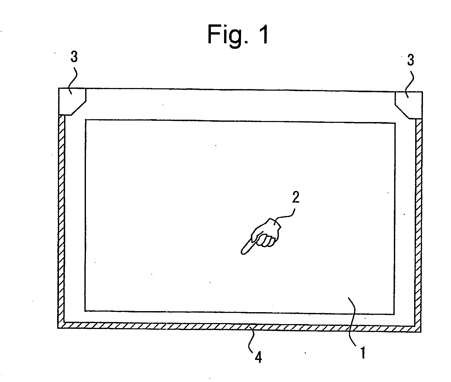
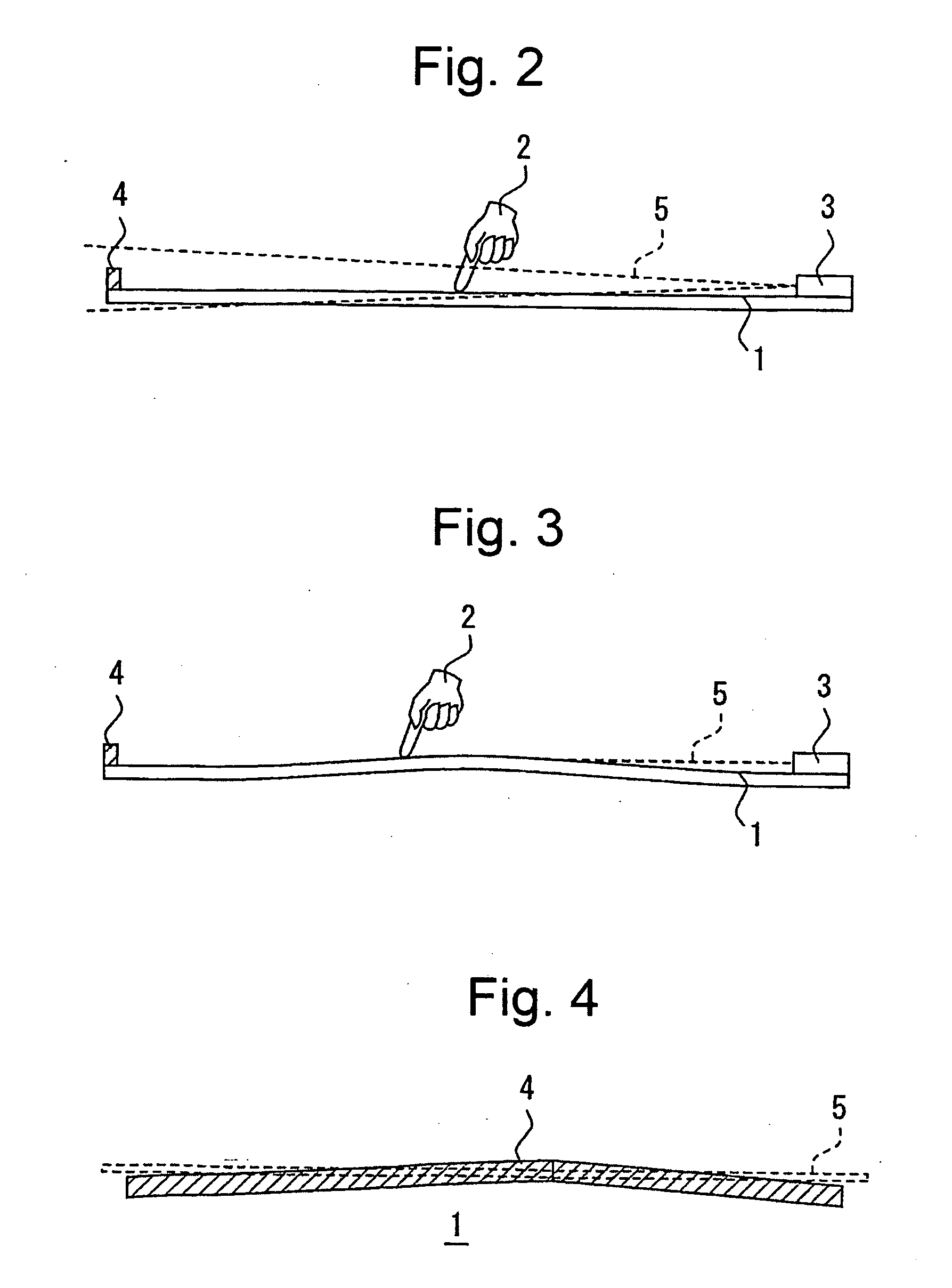
[0046] The present invention will now be explained in the following by using the exemplary embodiments described hereinbelow with referring to the appended drawings. FIG. 5 is a top plan of the position detection apparatus according to the present invention. In this drawing, the components with the same reference numerals as those shown in FIG. 1 denote the same components as those components shown in FIG. 1, and the basic configuration of the position detection apparatus of this invention is same as a conventional one shown in FIG. 1. Note that, although an example where a reflex reflection frame 4 is provided to at least three surrounding sides of the detection plane 1 and the position of a shade blocked by a pointing device 2 such as a finger is detected by the imaging sections 7 is mainly explained in FIG. 5, the present invention is not limited to this example, and the position detection apparatus of the present invention may also be configured such that the reflex reflection m...


PUM


Abstract

A position detection apparatus, with which the setting position adjustment of imaging sections is not required and the maintenance can be made easily, structuring of which can be realized with low-cost components, is provided. In the position detection apparatus, imaging sections (7), each of those which includes an area image sensor (70), in which light-sensitive elements are arrayed in a two-dimensional pattern, and an image formation lens (71), are placed to the lateral two points of a detection plane (1), respectively. A selection device (10) selects particular pixels corresponding to a particular field of view of a reflex reflection frame (4) or the like from the light-sensitive elements within a range of a given field of view having been imaged by the imaging sections (7). An image processing device (11) image-processes a particular image signal corresponding to the selected particular pixels and then outputs an indicating position coordinate of a pointing device (2).

Description

FIELD OF THE INVENTION [0001] The present invention relates to a position detection apparatus for detecting a pointing device that is situated on a detection plane, and particularly to a position detection apparatus in which an area image sensor is used in the imaging section. DESCRIPTION OF THE RELATED ART [0002] Position detection apparatuses for detecting a pointing device that is situated on a detection plane include the various types, such as an electromagnetic type, a pressure-sensitive type, an optical type and the like. An electromagnetic threshold detection apparatus is adapted to determine a two-dimensional coordinate from a planar distribution of radiant intensity of electromagnetic wave that is irradiated from a pointing device itself. For such a manner of detection, a dedicated pointing device that irradiates electromagnetic wave is required, and it is not possible to use fingers or the like for carrying out input operations. [0003] A position detection apparatus of the...

Claims


Application Information

Patent Timeline
IPC IPC(8): G06F3/042G06F3/033
CPCG06F3/0428G06F3/0418G06F3/0354G06F3/0304
Inventor OGAWA, YASUJITSUNEZAKI, KENJI
Owner MINATO ADVANCED TECH INC
Why Eureka
Try Eureka