
Electrically propulsed vehicle

a technology of electric propulsive vehicles and propulsive wheels, which is applied in the direction of driving parameters, power driven steering, applications, etc., can solve the problems of complex arrangement, heavy and expensive manufacturing, and even more complicated mechanical powertrains, etc., and achieves simple and robust effects

Inactive Publication Date: 2007-04-26
EL FOREST
View PDF21 Cites 25 Cited by
  • Summary
  • Abstract
  • Description
  • Claims
  • Application Information

AI Technical Summary

Benefits of technology

[0007] An advantage with the present invention is that it in a very simple and robust way provides a vehicle with constant multi wheel drive without advanced control systems, which system works in terrain.
[0008] Another advantage is that the design of the vehicle is simple and robust as the transmission of power from the engine is performed by electrical conductors instead of mechanical shaft arrangements. This is especially advantageous when the vehicle has more than two drive axles. Furthermore the design with many identical motor arrangements reduces the manufacturing costs.
[0009] Still another advantage is that the drive arrangement according to the invention makes it possible to considerably lower the weight of the vehicle.
[0010] Still another advantage is that the vehicle has considerably lower fuel consumption as compared to conventional vehicles which in turn gives right to reduced emission levels.

Problems solved by technology

Such arrangements are often very complicated, heavy and expensive to manufacture, they further require extensive maintenance.
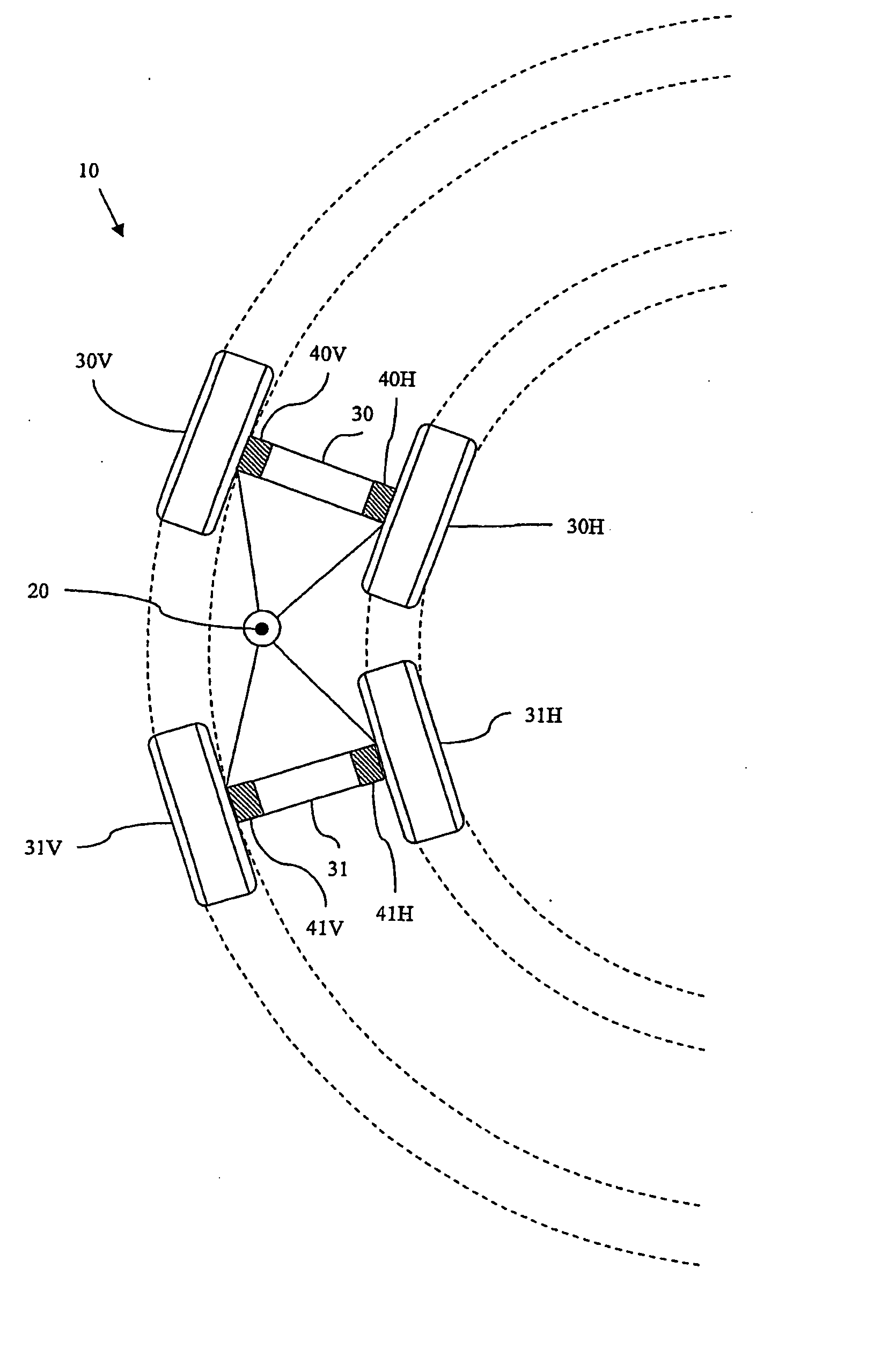
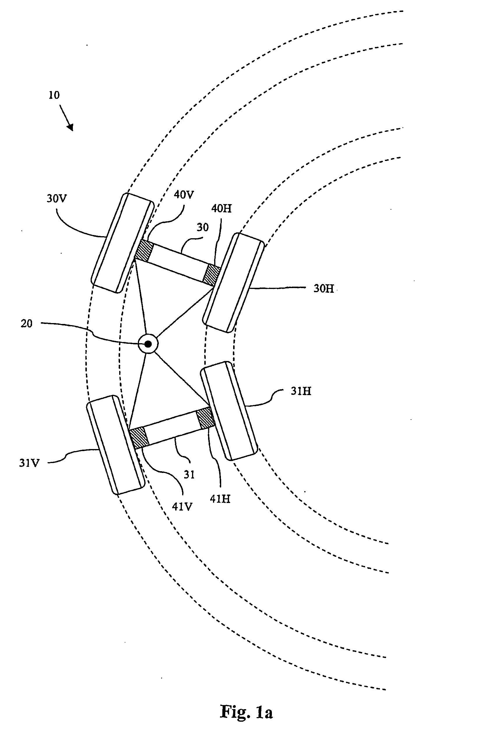
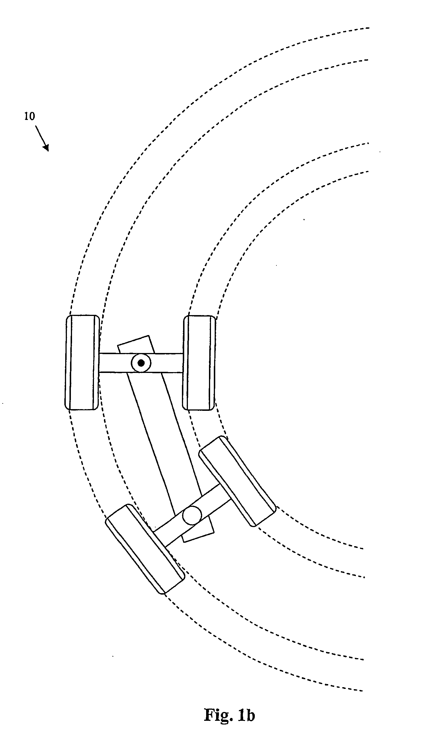
Such lock / break arrangements make the mechanical power train even more complicated, at the same time as the maneuverability is vastly deteriorated when they are activated.
Moreover the complex power train gives rise to considerable power losses, that in turn gives rise to higher fuel consumption.
The drawbacks of mechanical power trains are especially obvious for vehicles with more than two pair of drive wheels, such as forest vehicles with three or more pairs of drive wheels.
However, these trials have shown that power trains require a very complicated control system in order to achieve the differential function from a conventional mechanical power train, as the system may encounter a pressure drop if one wheel looses traction (looses the contact with the ground).
However, in order for this system to work, the ground must be essentially flat and where no skidding occurs, whereby such a system is practically useless in many situations where the ground is non-flat, e.g. for forest vehicles, which by definition operates in rough terrain where wheels regularly skids.

Method used


Image

  • Electrically propulsed vehicle
  • Electrically propulsed vehicle
  • Electrically propulsed vehicle

Examples


Embodiment Construction

[0018] Throughout the following description the phrase “side of the vehicle” is used with respect to the normal drive direction for the vehicle, and the same holds for the expressions left and right side, respectively. Moreover, for all embodiments, the present vehicle comprises a steering system that directly controls the steering angle between at least two of the drive axles of the vehicle, such as a conventional hydraulically or electrically powered power steering system.

[0019] The present invention is based on the understanding that, for a vehicle so arranged that the wheels on the right and left side, respectively, essentially follow the same wheel tracks during driving, the differential compensation for two consecutive drive axles can be obtained by a direct coupled control system with the steering angle between said drive axles as input. In the ideal case, during a turning operation all wheels on respective sides of such a vehicle travels along the same circle section with t...


PUM


Abstract

A vehicle has at least three drive axles each with a pair of drive wheels, a steering system that directly controls the steering angle between at least two of the drive axles. The vehicle is arranged so that all drive wheels on its right hand side and left hand side, respectively, essentially follow the same wheel tracks when it is driven. The frequency of rotation is individually controllable for each drive wheel. The vehicle includes differential compensating elements arranged to register the relative steering angle for each consecutive pair of drive axles, respectively, and the mutual frequency of rotation for the drive wheels of each drive axle is controlled by the registered relative steering angle associated with the axle. A drive axle arrangement for such a vehicle is also disclosed.

Description

[0001] The present invention relates to a vehicle with two or more drive axles, and specifically a vehicle so arranged that all wheels on the right and left hand side, respectively, always follow the same wheel track during driving. BACKGROUND OF THE INVENTION [0002] Commercially available articulated vehicles, such as forest vehicles and loading machines, are often equipped with conventional mechanical and / or hydraulic power trains. In such vehicles the force from an engine is transmitted to the drive wheels through an arrangement of shafts, hydraulics and gears. Such arrangements are often very complicated, heavy and expensive to manufacture, they further require extensive maintenance. Moreover a differential gear has to be arranged between each pair of drive wheels to make it possible for the vehicle to turn. However, in order to achieve acceptable availability, e.g. in difficult terrain, the power train has to be equipped with a differential lock / break arrangement that counterac...

Claims


Application Information

Patent Timeline
Patent Type & Authority Applications(United States)
IPC IPC(8): B62D11/02B60K7/00B60K17/356B62D11/00
CPCB60K7/0007B60K7/0015B60K17/356B60K2007/0092B62D11/001B60W2540/18B62D12/00
Inventor LUNDSTROM, LENNART
Owner EL FOREST
Learn More