
Spot weld fracture analysis method, program therefor, and analysis apparatus thereof

a technology of fracture analysis and analysis method, applied in the field of spot weld fracture analysis method, program therefor, and analysis apparatus thereof, can solve the problems of inability to appropriately analyze or predict, the analysis of a group of fractures does not take into account, and the possibility of fracture of the spot weld portion on a middle plate belonging to two groups, etc., to achieve the effect of high accuracy

Inactive Publication Date: 2007-04-26
TOYOTA JIDOSHA KK
View PDF3 Cites 28 Cited by
  • Summary
  • Abstract
  • Description
  • Claims
  • Application Information

AI Technical Summary

Benefits of technology

[0009] It is an object of the invention to provide a fracture analysis method for a spot weld portion in which a fracture analysis can be performed at high accuracy with respect to spot weld portions of three or more plates that are spot-welded at a common welding point and a computer-readable program for executing the method as well as a spot weld fracture analysis apparatus.

Problems solved by technology

However, in the case where the fracture analysis method is directly utilized, the fracture analysis on a group does not take into account the element force of the beam element in another group.
Therefore, a problem is that the possibility of fracture of the spot weld portion on a middle plate belonging to two groups (i.e., a middle plate that forms groups with two plates (inside and outside plates)) cannot be appropriately analyzed or predicted.

Method used


Image

  • Spot weld fracture analysis method, program therefor, and analysis apparatus thereof
  • Spot weld fracture analysis method, program therefor, and analysis apparatus thereof
  • Spot weld fracture analysis method, program therefor, and analysis apparatus thereof

Examples


Embodiment Construction

[0024] Hereinafter, best modes for carrying out the invention will be described with reference to the drawings.

[0025] A spot weld fracture analysis apparatus in accordance with the embodiment of the invention is realized by a computer (including a supercomputer) in which software that realizes a spot weld fracture analysis method described in detail below is incorporated. This software may be developed as an entirely novel group of software, but can also be created on the basis of an existing analysis software set (e.g., LS-DYNA, PAM-CRASH (both are registered trademarks in Japan), etc.). Or, it may also be developed as a software set that cooperates with an existing analysis software set, such as LS-DYNA, PAM-CRASH, etc., and provides additional functions.

[0026] A computer terminal that a user directly utilizes has, as user interfaces, for example, a mouse and a keyboard, and has a display that displays models for analysis, analysis results, etc. Besides, this computer terminal m...


PUM

PropertyMeasurementUnit
fracture analysisaaaaaaaaaa
forceaaaaaaaaaa
forcesaaaaaaaaaa

Abstract

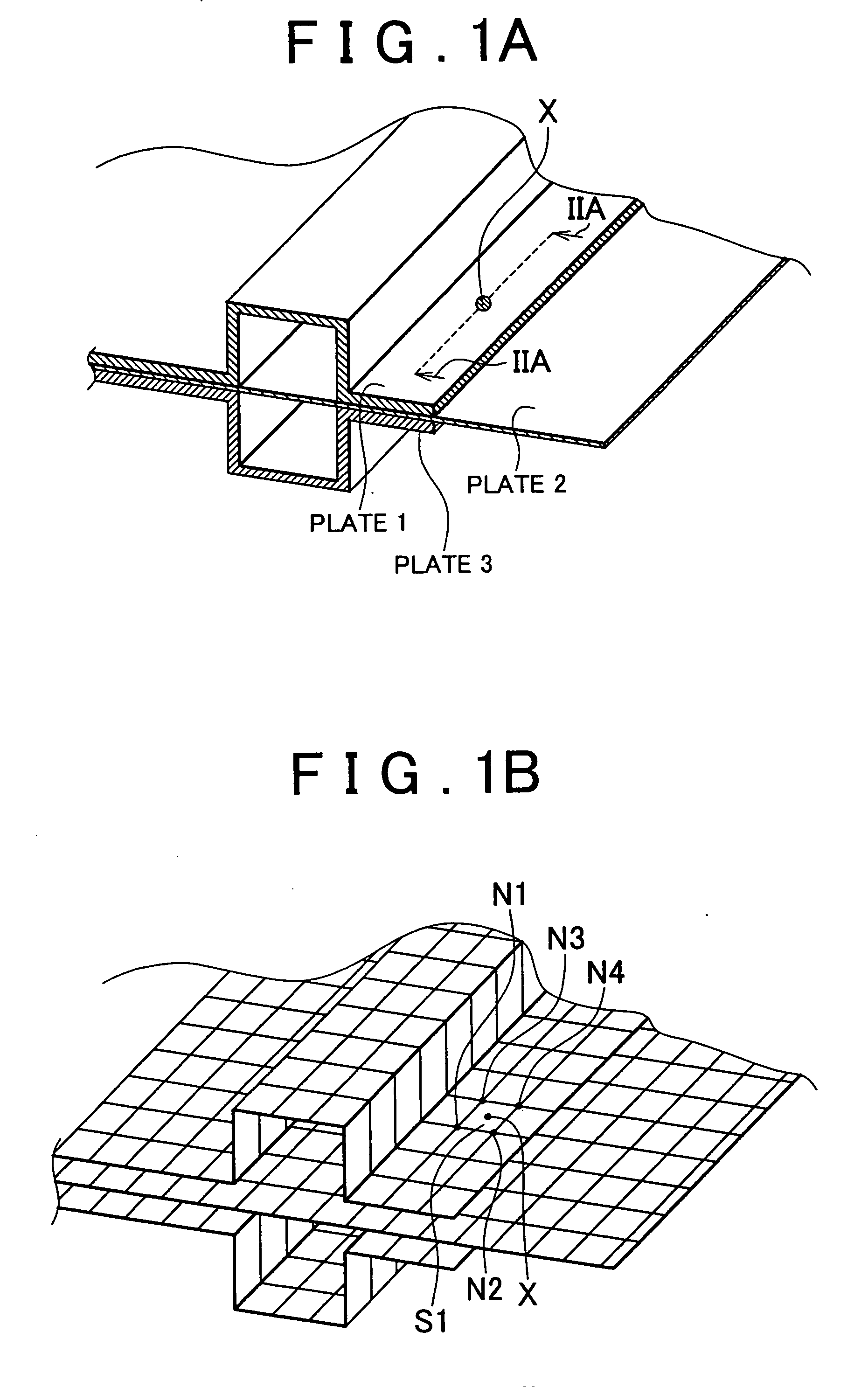
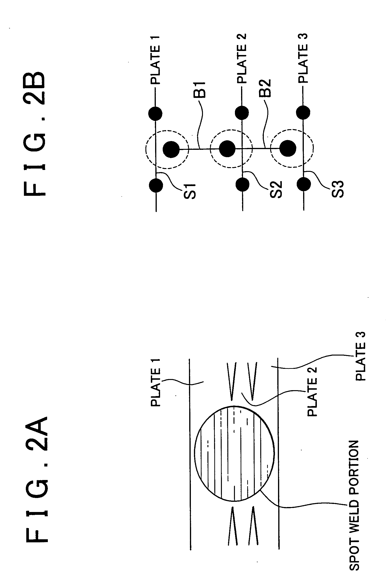
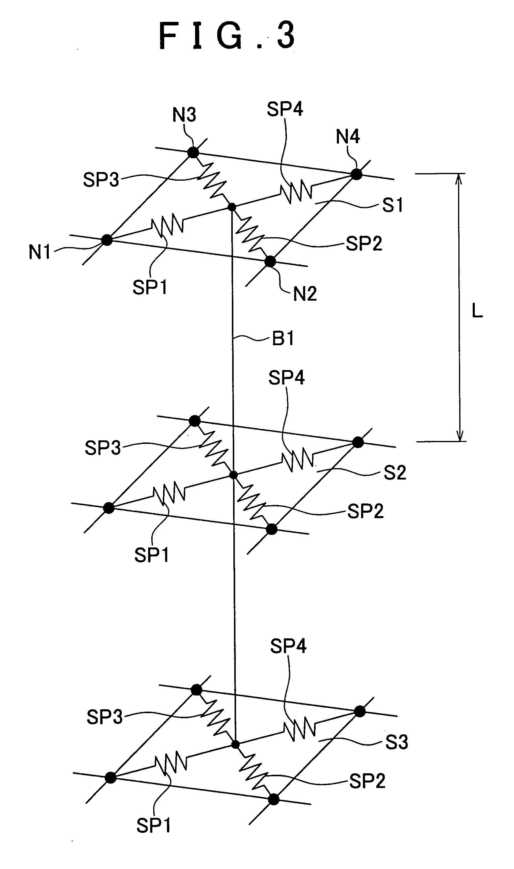
A spot weld fracture analysis method for a spot weld portion of three or more mutually superimposed plates that are spot-welded at a common welding point comprises an analysis step of executing an analysis by using a finite element model in which each plate is modeled by shell elements, and the shell elements corresponding to a spot weld point position of each plate are individually interconnected via beam elements, and a prediction step of finding an element force of a beam element that acts on a shell element relevant to a middle plate from a difference between the element forces of two beam elements connected to the shell element on a basis of the analysis result, and predicting a possibility of fracture of a spot weld between the middle plate and an adjacent plate by using the difference element force found from the difference.

Description

INCORPORATION BY REFERENCE [0001] The disclosure of Japanese Patent Application No. 2005-305717 filed on Oct. 20, 2005, including the specification, drawings and abstract, is incorporated herein by reference in its entirety. BACKGROUND OF THE INVENTION [0002] 1. Field of Invention [0003] The invention relates to a fracture analysis method for a spot weld portion of three or more mutually superimposed plates that are spot-welded at a common welding point and a computer-readable program for executing the method as well as a spot weld fracture analysis apparatus. [0004] 2. Description of Related Art [0005] There is a known fatigue life prediction method for a spot-welded structure characterized in that two plates are joined to form a spot-welded structure, and that a finite element analysis-purpose shell model for the spot-welded structure is created, and that using the created purpose shell model, a finite element linear elastic analysis is performed to calculate the share load of a n...

Claims


Application Information

Patent Timeline
Patent Type & Authority Applications(United States)
IPC IPC(8): A47J36/02
CPCB23K11/34B23K31/12G01N3/00G06F17/5018G01N2203/0216G01N2203/0296G01N2203/0073G06F30/23
Inventor KUMAGAI, KOUSHI
Owner TOYOTA JIDOSHA KK
Learn More