Power core devices and methods of making thereof

a technology of power core and power core, which is applied in the direction of printed capacitor incorporation, printed circuit non-printed electric component association, printed capacitor incorporation, etc., can solve the problems of power overshoot, microprocessor voltage drop or power droop, and ic malfunction

Active Publication Date: 2007-04-26
CHEMTRON RES
View PDF19 Cites 102 Cited by
  • Summary
  • Abstract
  • Description
  • Claims
  • Application Information

AI Technical Summary

Problems solved by technology

As semiconductor devices including integrated circuits (IC) operate at higher frequencies, higher data rates and lower voltages, managing noise in the power and ground (return) lines and supplying sufficient current to accommodate faster circuit switching become increasingly important problems requiring low impedance in the power distribution system.
If the response time of the voltage supply is too slow, the microprocessor will experience a voltage drop or power droop that will exceed the allowable ripple voltage and noise margin and the IC will malfunction.
Additionally, as the IC powers up, a slow response time will result in power overshoot.
This leads to increased circuit loop inductance, which in turn increases impedance, constraining current flow, thereby reducing the beneficial effects of the surface mounted capacitors.
However, such an approach does not necessarily improve voltage response.
Simply placing the capacitor laminate closer to the IC may not be sufficient because the total capacitance available may be insufficient.

Method used


Image

  • Power core devices and methods of making thereof
  • Power core devices and methods of making thereof
  • Power core devices and methods of making thereof

Examples


Embodiment Construction

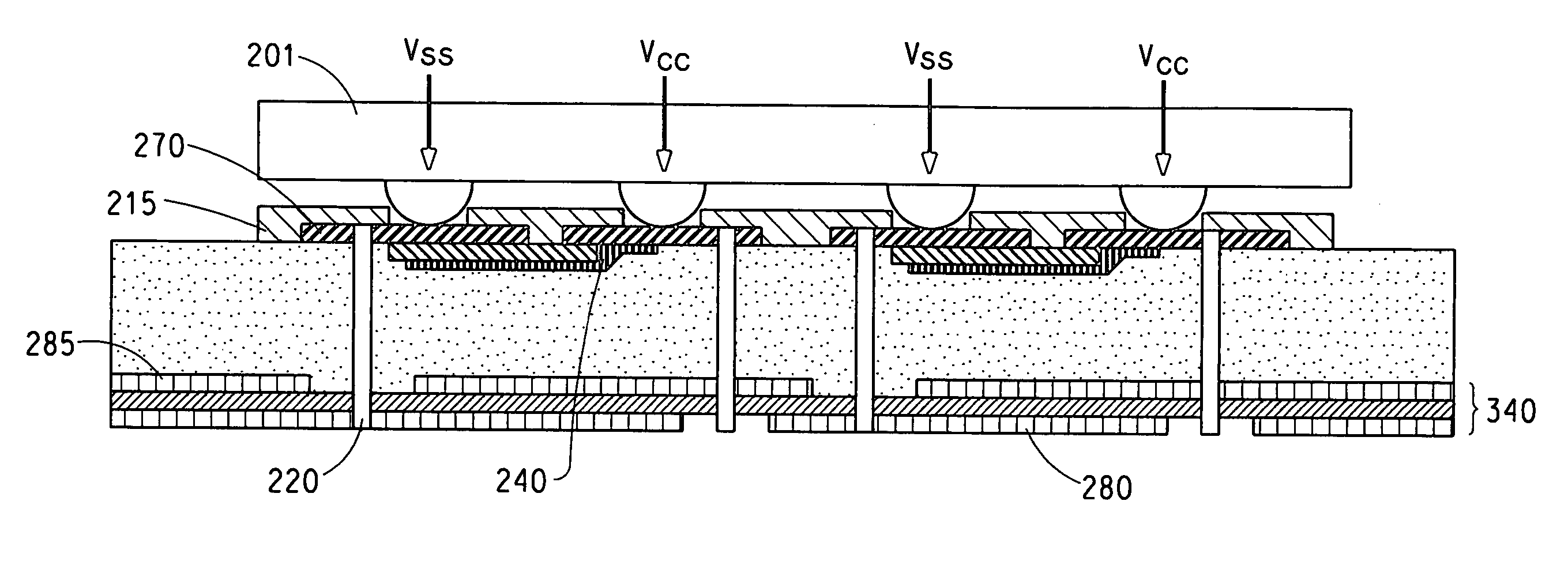
[0025] According to a first embodiment, a design and manufacturing method of a power core device is disclosed in which singulated capacitors with electrodes on the outer layer and planar capacitors are connected in parallel and embedded within a laminate structure to create a power core structure. The power core structure may be interconnected to at least one signal layer. Singulated capacitors may be defined as individual capacitors formed on metal. Typically, the metal is a metal foil. Although we use the term “foil” herein, it is understood that foil encompasses a general metal layer, plated metal, sputtered metal, etc. The singulated capacitors in the power core structure are designed to be on the outer layer of the device with the foil portion of the first electrode and the foil second electrode in the same plane on the outer layer so that the Vcc (power) terminals and the Vss (ground) terminals of the semiconductor device, such as a microprocessor, are aligned with and may be ...


PUM


Abstract

A device comprising a power core wherein said power core comprises: at least one embedded singulated capacitor layer containing at least one embedded singulated capacitor wherein said embedded singulated capacitor comprises at least a first electrode and a second electrode and wherein said embedded singulated capacitor is positioned on the outer layer of the power core with both first and second electrodes of the capacitor on the outer layer of the power core so that at least one Vcc (power) terminal and at least one Vss (ground) terminal of a semiconductor device can be directly connected to at least one first and at least one second electrode, respectively.

Description

FIELD OF THE INVENTION [0001] The technical field relates to devices having both low inductance and high capacitance functions, and methods of incorporating such devices in power core packages, including organic dielectric laminates and printed wiring boards. BACKGROUND OF THE INVENTION [0002] As semiconductor devices including integrated circuits (IC) operate at higher frequencies, higher data rates and lower voltages, managing noise in the power and ground (return) lines and supplying sufficient current to accommodate faster circuit switching become increasingly important problems requiring low impedance in the power distribution system. In order to provide low-noise and stable power to the IC, impedance in conventional circuits is reduced by the use of additional surface mount capacitors interconnected in parallel. The higher operating frequencies (higher IC switching speeds) mean that voltage response times to the IC must be faster. Lower operating voltages require that allowabl...

Claims


Application Information

Patent Timeline
Patent Type & Authority Applications(United States)
IPC IPC(8): H01L23/52H01L21/00
CPCH01L23/49822H01L23/49838H01L23/50H01L2924/01012H01L2924/0102H01L2924/01057H01L2924/01078H01L2924/09701H01L2924/3011H05K1/113H05K1/162H05K2201/09309H05K2201/09763H05K2201/10734H01L2224/16225H01L2924/01019H05K1/16H05K1/18H01F27/28
Inventor BORLAND, WILLIAM J.FERGUSON, SAUL
Owner CHEMTRON RES
Why Eureka
Try Eureka