Sealing device

Inactive Publication Date: 2007-04-26
UCHIYAMA MFG
View PDF5 Cites 11 Cited by
  • Summary
  • Abstract
  • Description
  • Claims
  • Application Information

AI Technical Summary

Benefits of technology

[0004] The present invention is proposed in view of the above-mentioned problems and the object of the present invention is to provide a newly developed sealing device which allows the running torque to be reduced, the sealing ability to be superior and the seal duration to be long.
[0006] When the sealing device of the present invention is used for the wheel bearing unit of vehicles, an axial lip and a flange portion of a slinger are elastically and slidably contacted, so that waste water and dust are prevented from being entered from outside into the sealed portion (bearing portion) and further lubricant (such as grease) charged in the sealed portion is prevented from leaking into outside. The labyrinth of a small gap extending into the length area along the axial direction is formed between a base portion of the axial lip and the peripheral surface of the fitting cylindrical portion of the slinger. Therefore, because of the labyrinth and the axial lip elastically and slidably contacting with the slinger, the lubricant is prevented from leaking outside. Further, the elastic seal member and the peripheral surface of the fitting cylindrical portion of the slinger do not contact each other and the radial lip does not present, therefore, the running loading torque applied to the rotatable member becomes small, thereby contributing energy efficiency of vehicles. The elastic and slidable contact of the axial lip and the flange portion of the slinger is into the axial direction (thrust direction), therefore, the running torque caused by the elastic and slidable contact does not become so large.
[0007] Further according to the present invention in which a plurality of axial lips are provided, the sealing ability like prevention of dust invasion and prevention of leakage of lubricant is more improved. Still further according to the present invention in which the outer lip provided at the elastic seal member elastically and slidably contacts with the outer surface of the tapered portion formed by bending the peripheral edge of the flange portion of the slinger, waste water and dust are prevented from entering from outside at the inlet portion of the space formed with the slinger, and the elastic seal member and the core member, so that they do not stay in the space. Therefore, it is prevented that the staying dust is involved into the elastically and slidably contacting portion of the axial lip and the flange portion of the slinger, so that the axial lip cannot be worn away and its sealing ability cannot be deteriorated.
[0008] Lack of mutual retention of the members (slinger, and elastic seal member / core member) without having a radial lip is compensated by the elastic contact of the outer lip and the tapered surface, thereby having a good assembling ability as a pack seal and preventing disassembling of the members. Further, the product can be packed while keeping the concentricity of the slinger, the elastic seal member and the core member to achieve a good management and conveying ability. Further according to the present invention, the member in which the slinger is fixedly fitted is a rotatable member and the member in which the elastic seal member and the core member are fixedly fitted is a stationary member, so that the sealing device can be used for a general purpose bearing unit, thereby obtaining more effect and improving usefulness.

Problems solved by technology

However, such incursion cannot be avoided with time, the entered dust is surrounded with the slinger and the core member to be piled up in the space divided with the axial lip.
The piled dust is involved into the elastically and slidably contacting portion of the axial lip with the flange portion of the slinger to cause the axial lip worn away, thereby deteriorating the seal duration as a sealing device.

Method used


Image

  • Sealing device
  • Sealing device
  • Sealing device

Examples


Embodiment Construction

[0011] The preferred embodiment of the present invention is explained hereinafter referring to the attached drawings.

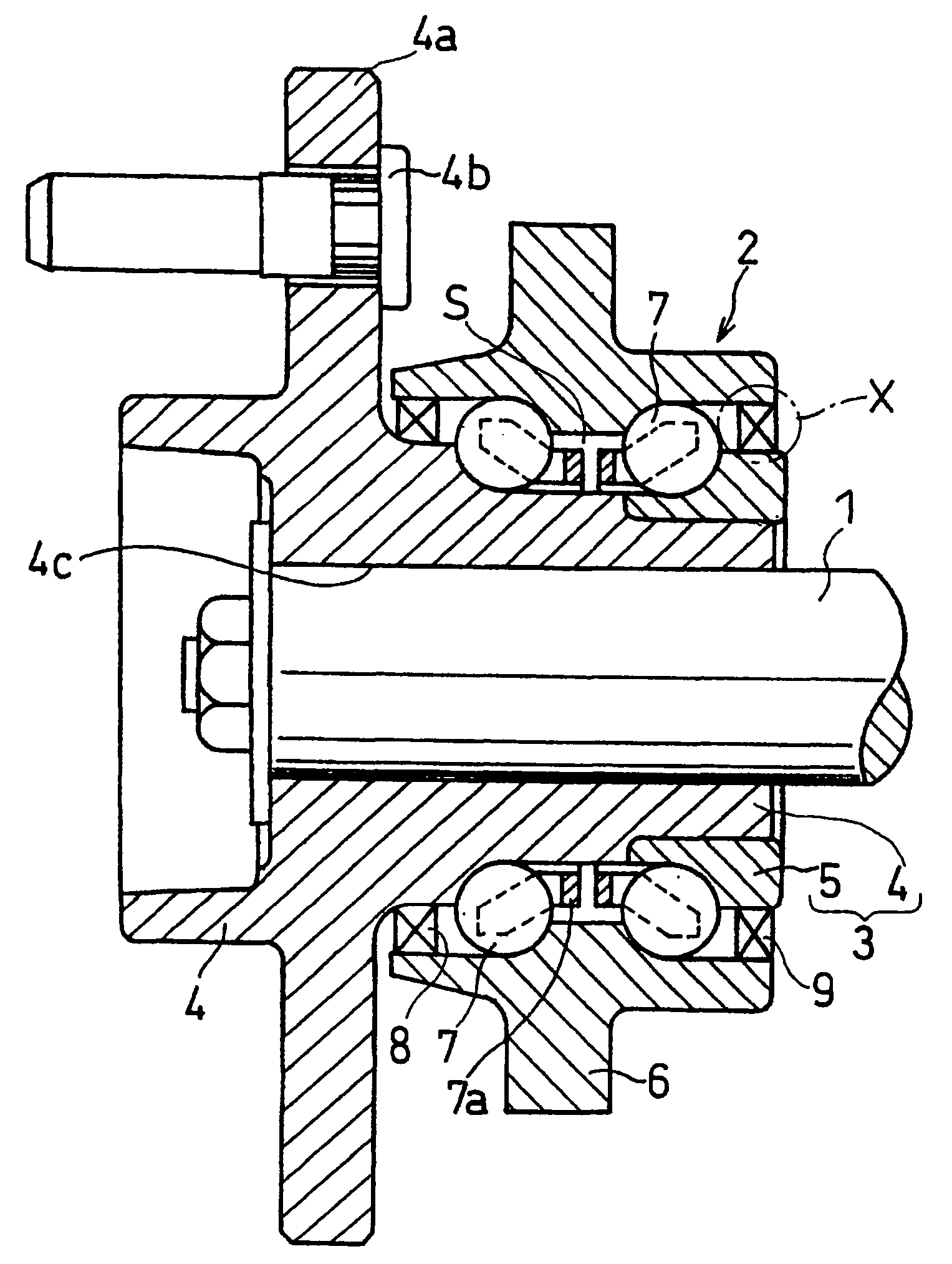
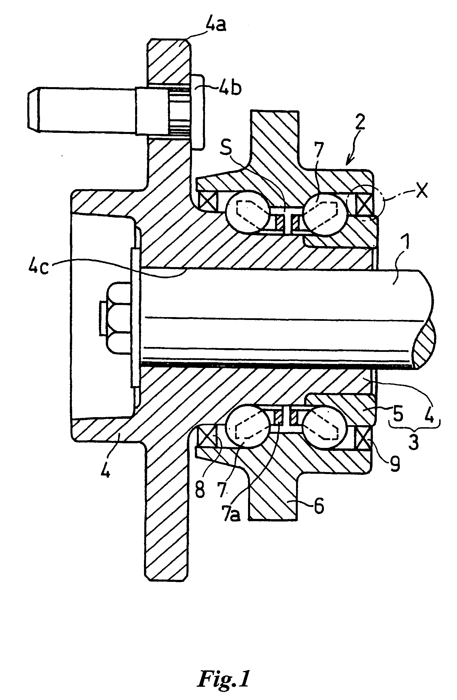
[0012]FIG. 1 shows one embodiment of the structure in which a vehicle wheel is supported for a driving shaft 1 with a ball bearing unit (hub bearing) 2. A tire wheel (not shown) is fixed to a hub flange 4a of a hub wheel 4 constituting an inner ring (rotatable member) 3 by means of a bolt 4b. The reference numeral 4c indicates a spline hole formed in the hub wheel 4 and the driving shaft 1 is spline fitted in the hole 4c and is integrally fixed to the hub wheel 4, thereby transmitting the rotating drive force of driving shaft 1 into the tire wheel via the hub wheel 4. The reference numeral 5 indicates an inner ring member, which constitutes the inner ring 3 together with the hub wheel 4.

[0013] The reference numeral 6 indicates an outer ring (stationary member) which is attached and fixed to the vehicle suspension (not shown) with bolts (not shown). Two rows of rolli...


PUM


Abstract

A sealing device for sealing a space between two members relatively rotating in concentricity, comprising: a slinger fixedly fitted into one of the members, a core member fixedly fitted into the other of the members, and an elastic seal member attached to the core member, the elastic seal member having a seal lip elastically and slidably contacting with the slinger. The slinger has a fitting cylindrical portion to be fitted into the one member and a flange portion extending from the fitting cylindrical portion in its radial direction, whereas the seal lip has a base portion fixed to the core member and constitutes an axial lip elastically and slidably contacting with the inner surface of the flange portion of the slinger. The peripheral surface of the fitting cylindrical portion of the slinger and the corresponding peripheral surface of the base portion of the elastic seal member closely face each other with substantially constant space along the axial direction of the slinger, thereby constituting labyrinth construction between them.

Description

FIELD OF THE INVENTION [0001] The present invention relates to a sealing device interposed into a necessary portion to be sealed between a stationary member and a rotating member like a bearing unit of a wheel suspension of vehicles, more particularly relates to a sealing device constructed such that a slinger is assembled with a core member for fixedly holding an elastic seal member which elastically and slidably contacts with the slinger. PRIOR ART [0002] The above-mentioned sealing device is so called as a pack seal or a combination seal, a slinger and a core member for fixedly holding the elastic seal member are assembled to form a seal ring, and the resultant product is supplied to a customer. The prior arts JP-A-9-292032, JP-A-2003-314698, and JP-A-2005-524807 disclose such a sealing device. The sealing device is comprised of a slinger with an L-shaped cross-section which is fixedly fitted in one of two members rotating relatively and concentrically, a core member with an L-sh...

Claims


Application Information

Patent Timeline
IPC IPC(8): F16J15/00F16C33/78F16J15/3232
CPCF16C33/7883F16J15/3264F16C19/186F16C41/04F16C2326/02
Inventor SHIBAYAMA, MASANORIISHII, KAZUO
Owner UCHIYAMA MFG
Why Eureka
Try Eureka