Supercharge Your Innovation With Domain-Expert AI Agents!

System and method for position detection of a terminal in a network

a terminal and network technology, applied in the direction of direction finders, direction finders using radio waves, instruments, etc., can solve the problems of difficult map generation, terminal position cannot be detected, and degrading the accuracy of position detection, so as to shorten the time for position detection

Active Publication Date: 2007-04-26
MAXELL HLDG LTD
View PDF5 Cites 3 Cited by
  • Summary
  • Abstract
  • Description
  • Claims
  • Application Information

AI Technical Summary

Benefits of technology

This approach reduces position detection time, improves accuracy, and allows for automatic database updates, enabling faster and more accurate position determination without the need for manual map generation or additional terminal functions.

Problems solved by technology

In the position detection method using GPS or DGPS, at least radio waves from GPS satellites need to be received, so that a position of a terminal cannot be detected where GPS signals cannot be received.
Unfortunately, In the position detection method using received electric field, large errors occur due to level fluctuation such as multipath fading and shadowing, thus degrading accuracy of the position detection.
Unfortunately, in this method, the maps are hard to generate, and need to be generated again when the neighboring layout changes.
In this document, since a distance estimated from the received electric field strength has a large error, the measurement accuracy is improved using the fact that a round-trip propagation time between the base station and terminal in communication with each other has a small error.
As a result, many calculation processes are required to take a long time until the position detection.

Method used


Image

  • System and method for position detection of a terminal in a network
  • System and method for position detection of a terminal in a network
  • System and method for position detection of a terminal in a network

Examples


Embodiment Construction

[0034] An invention for system and method for position detection of a terminal in a network is disclosed. Numerous specific details are set forth in order to provide a thorough understanding of the present invention. It will be understood, however, to one skilled in the art, that the present invention may be practiced with other specific details.

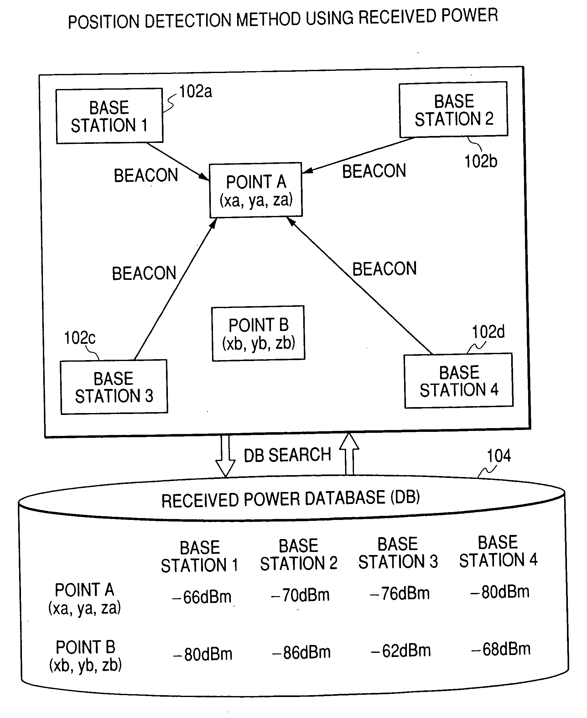
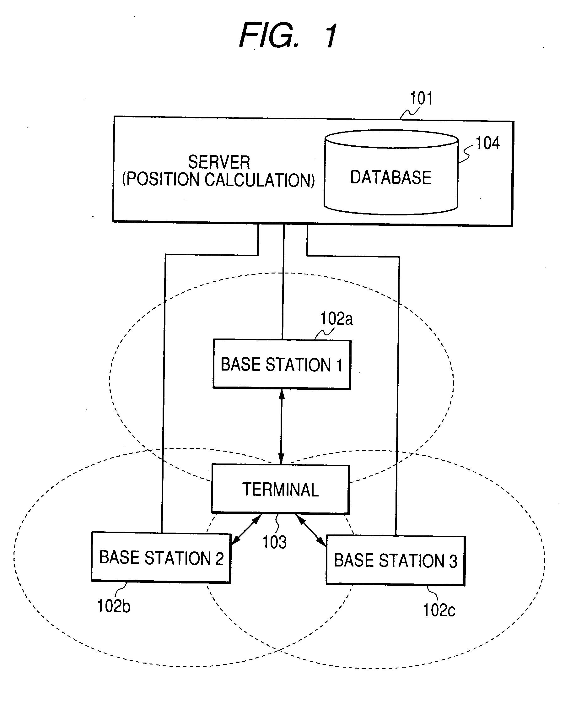
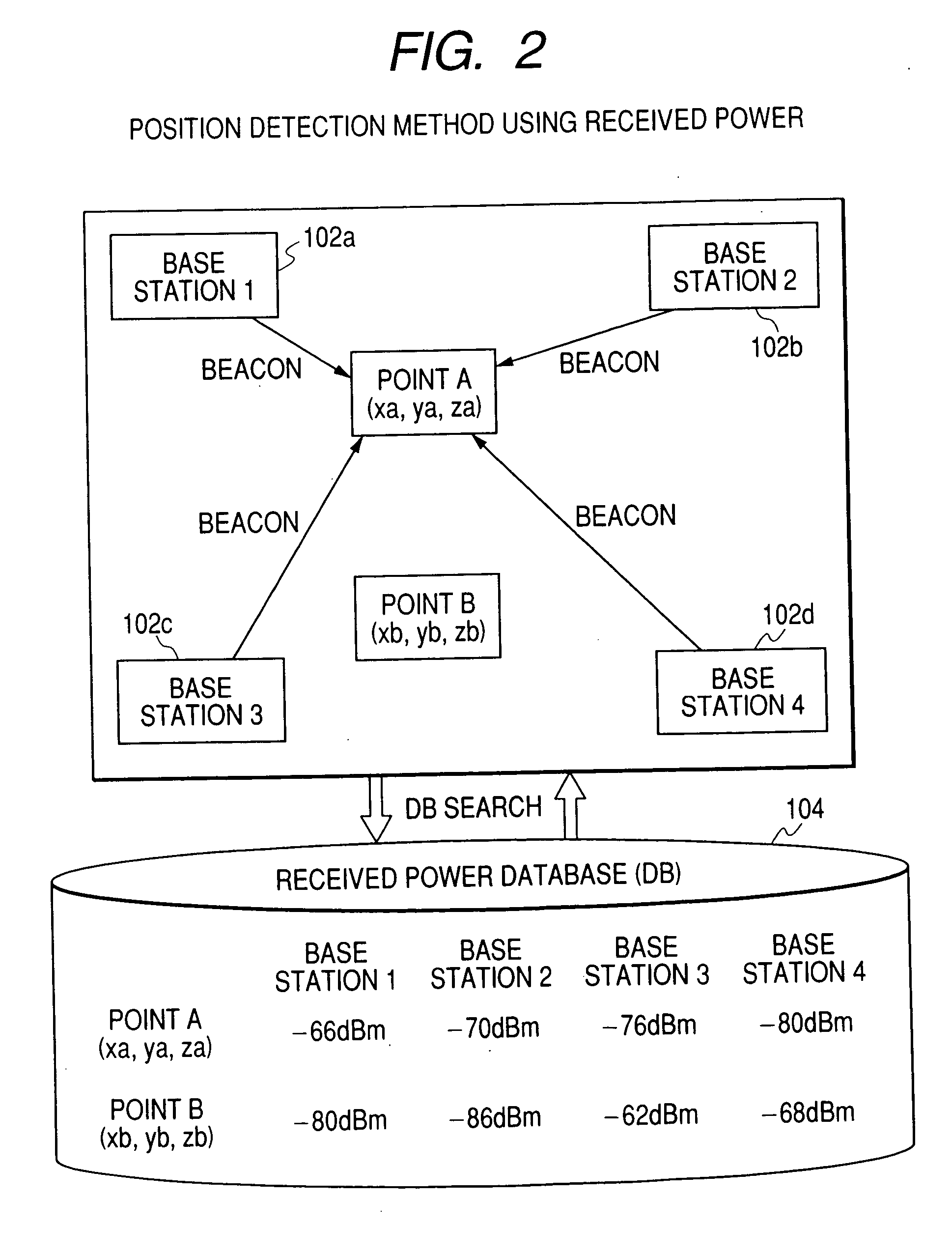
[0035]FIG. 1 shows a configuration of a radio communications system of the present invention and a system configuration for detecting a position of a terminal.

[0036] The radio communications system includes a plurality of base stations 102a, 102b, and 102c, a terminal 103 within coverage of the base stations 102a, 102b, and 102c, and a server 101 having in its storage a database 104 for collecting information required for calculating a position of the terminal 103. A system configuration in which the database and the function for calculating the position are contained in the terminal 103 or any one of the base stations 102a, 102b, and 102c...


PUM


Abstract

In a position detection system for detecting a position of a terminal apparatus of a radio communications system, a position detection time is shortened using a position detection method for determining signal times-of-arrival between the terminal apparatus and base stations neighboring the terminal apparatus. According to the present invention, means for generating a database in which received power information about signals transferred between the terminal apparatus and the base stations neighboring the terminal apparatus corresponds to position information about the terminal apparatus, and for determining the position information by searching received power information obtained in the position detection from the database, and means for determining the position by use of signal times-of-arrival are executed in parallel. Then, the use of a result of the means which has detected the position earlier than another means shortens the position detection time.

Description

CROSS-REFERENCE TO RELATED APPLICATION [0001] This application is a continuation application of U.S. application Ser. No. 10 / 866,722 filed Jun. 15, 2004. Priority is claimed based on U.S. application Ser. No. 10 / 866,722 filed Jun. 15, 2004, which claims the priority of Japanese Patent Application No. 2003-353096 filed on Oct. 14, 2003, all of which is incorporated by reference.BACKGROUND OF THE INVENTION [0002] 1. Field of the Invention [0003] The present invention relates to a radio communications system and a position detection method for achieving position detection of a mobile or fixed terminal. [0004] 2. Discussion of Background [0005] A GPS (Global Positioning System) is well known as recent mobile communications systems represented by, for example, mobile phones. GPS is such that a GPS receiver receives radio waves from a plurality of GPS satellites to determine distances from the satellites and then to calculate a reception position of a terminal according to trilateration. ...

Claims


Application Information

Patent Timeline
Patent Type & Authority Applications(United States)
IPC IPC(8): G01S3/02G01S5/02G01S5/06G01S5/10H04W60/00H04W64/00
CPCG01S5/0252G01S5/0268G01S5/10G01S5/02521
Inventor TAMAKI, TSUYOSHIOGINO, ATSUSHIUTA, TAKAKIYAMASAKI, RYOTA
Owner MAXELL HLDG LTD
Features
  • R&D
  • Intellectual Property
  • Life Sciences
  • Materials
  • Tech Scout
  • Unparalleled Data Quality
  • Higher Quality Content
  • 60% Fewer Hallucinations
Learn More