Tactile force sense information display system and method

a technology of tactile force and information display system, applied in the field of tactile force sense information display system and method, can solve the problems of limiting the range of use of space, limiting the human motion, and difficulty in continuously presenting haptic information of torque, force or the like in the same direction, so as to save energy and efficiently present haptic information , the effect of miniaturizing the haptic presentation system

Inactive Publication Date: 2007-04-26
NAT INST OF ADVANCED IND SCI & TECH
View PDF2 Cites 115 Cited by
  • Summary
  • Abstract
  • Description
  • Claims
  • Application Information

AI Technical Summary

Benefits of technology

[0020] When the haptic information presentation system of the invention and the haptic information presentation method are carried out, special effects listed below can be obtained.
[0021] (1) It becomes possible to continuously or intermittently present the haptic information of the torque, force and the like in the same direction, which has been difficult in a conventional man-machine interface which is of a non-grounding type and has no reaction base on the body.
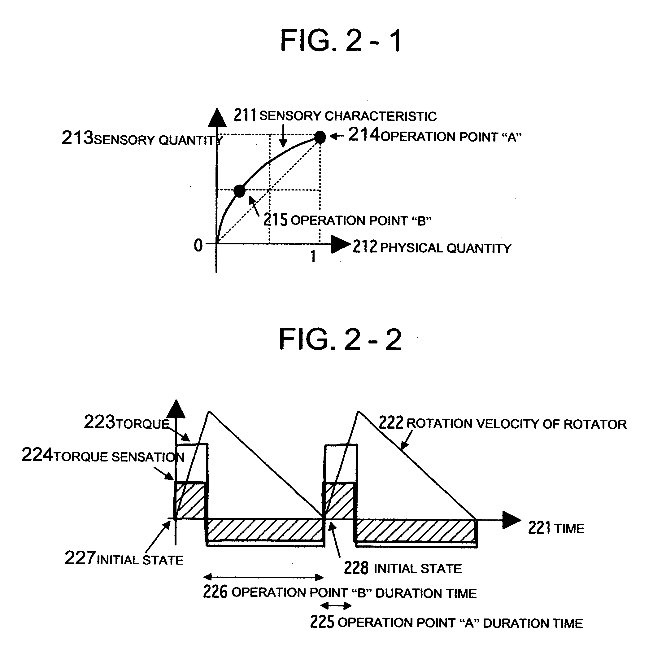
[0022] (2) By using human sensory characteristics and illusion, it becomes possible to present the haptic sensory-physical characteristics of the torque, force or the like, which can not exist physically, to a person.
[0023] (3) By using the human sensory characteristics, it becomes possible to present the haptic information efficiently while energy is saved, and a miniaturized haptic presentation system can be realized.
[0024] (4) In order to present a vibration sensation, a torque sensation, and a force sensation, a device corresponding to each of them is conventionally required. However, according to the invention, it becomes possible to simultaneously present one or more of the vibration sensation, the torque sensation, and the force sensation by one mechanism of the eccentric rotators, various haptic information can be presented, and the presentation system can be miniaturized.
[0025] (5) By carrying out the invention, it is possible to realize a useful man-machine interface, an interface between a robot and a machine, an interface between an animal and a machine, and the like, which can be mounted on an equipment used in the field of VR (Virtual Reality), an equipment used in the field of game, a cellular phone, a portable navigation equipment, a PDA (Personal Digital Assistant) and the like. For example, in the field of the VR, the existence of an object in a virtual space or the shock due to a collision can be presented by presenting a force to a person through the man-machine interface or by giving a resisting force or reaction force. Besides, by mounting the interface on the cellular phone, portable navigation equipment, PDA, or the like, various instructions, guides and the like, which have not existed conventionally, can be realized through the skin of an operator.

Problems solved by technology

With respect to a conventional haptic device in the VR, in the haptic presentation of a tensile force or reaction force, a haptic presentation part in contact with a human sense organ and a haptic presentation system main body are connected to each other by a wire or an arm, and there has been a disadvantage that the existence of the wire, arm or the like restricts the human motion.
Besides, since use is limited to an effective space in which the haptic presentation system main body and the haptic presentation part are connected to each other by the wire or the arm, there has been a limitation in the expanse of the space which can be used.
However, in this type of presentation device, the rotation velocity (angular velocity) of a motor is controlled so that a torque is presented by a temporal change of an angular momentum vector, and it has been difficult to continuously present haptic information of torque, force or the like in the same direction.
However, in the gimbal structure, there are problems that the direction of a torque which can be presented is limited, the structure becomes complicated, and the control becomes troublesome.
However, there are such problems to be solved that haptic information is made to be capable of being continuously presented, and a force sensation other than the torque is made to be capable of being presented.

Method used


Image

  • Tactile force sense information display system and method
  • Tactile force sense information display system and method
  • Tactile force sense information display system and method

Examples


applied example 1

[0068]FIG. 14 is a view showing a sheet-shaped eccentric rotator array 880 in which one of the eccentric rotator 711 of FIG. 10-1, the twin eccentric rotator 811 of FIG. 11-1, and the twin eccentric rotator arranged in the three-dimensional space of FIG. 13 is arranged like a sheet in a three-dimensional plane. A practicing method of a drive portion of the twin eccentric rotator may be a molecular motor or a piezoelectric element, and anything may be used as long as an objective physical quantity can be presented.

[0069]FIG. 15 is a view showing a glove-shaped eccentric rotator array 890 in which the sheet-shaped eccentric rotator array 880 is formed into a glove shape. By suitably controlling the rotation of each eccentric rotator, the vibration sensation, torque sensation, and force sensation of various patterns in space and time can be presented onto a palm.

[0070] Incidentally, the sheet-shaped eccentric rotator array 880 and the glove-shaped eccentric rotator array 890 are mere...

applied example 2

[0124]FIG. 31 is a view showing another applied example of the groove-shaped eccentric rotator array 890 of FIG. 15 and is a view showing a groove-shaped eccentric rotator array 3110 in which a sheet-shaped eccentric rotator array 3111 is formed into a groove shape. In FIG. 31, rotators are arranged like a grid, and only eccentric rotators 3170a to 3173a, and 3170b to 3177b rotate. By this, by suitably controlling the rotations of the eccentric rotators 3170a to 3173a, and 3170b to 3177b of the groove-shaped eccentric rotator array 3110, haptic information of a virtual twist as a spatial expansion can be presented onto the palm. In more detail, a large torque is presented in the same direction by the eccentric rotators 3170a to 3173a, so that a large resultant torque 315a to twist the center part of the palm counterclockwise is presented. Besides, a small torque is presented in the same direction by the eccentric rotators 3170b to 3177b, so that a resultant torque 315b to twist the ...

modified examples

[0137] Hereinafter, modified examples of the operation principles 1 to 3 will be described.

[0138]FIG. 37 is a view showing a rough structure of a modified example of the haptic information presentation method of FIG. 11-4 described in the embodiment. In FIG. 11-4, the two eccentric rotators are synchronously rotated in the opposite directions, and the force to linearly generate the simple harmonic oscillations in an arbitrary direction is synthesized. FIG. 37 is a view showing a piezoelectric matrix 3730 as an oscillator in which instead of the eccentric rotators, piezoelectric elements 3701 are used. A piezoelectric array 3710 is constructed in which the plural piezoelectric elements 3701 are laminated in an x-direction in the drawing, a piezoelectric array 3720 is constructed in which the plural piezoelectric elements 3701 are laminated in a y-direction in the drawing, and the piezoelectric arrays 3710 and 3720 are alternatively arranged in the x and the y directions in the oscil...


PUM


Abstract

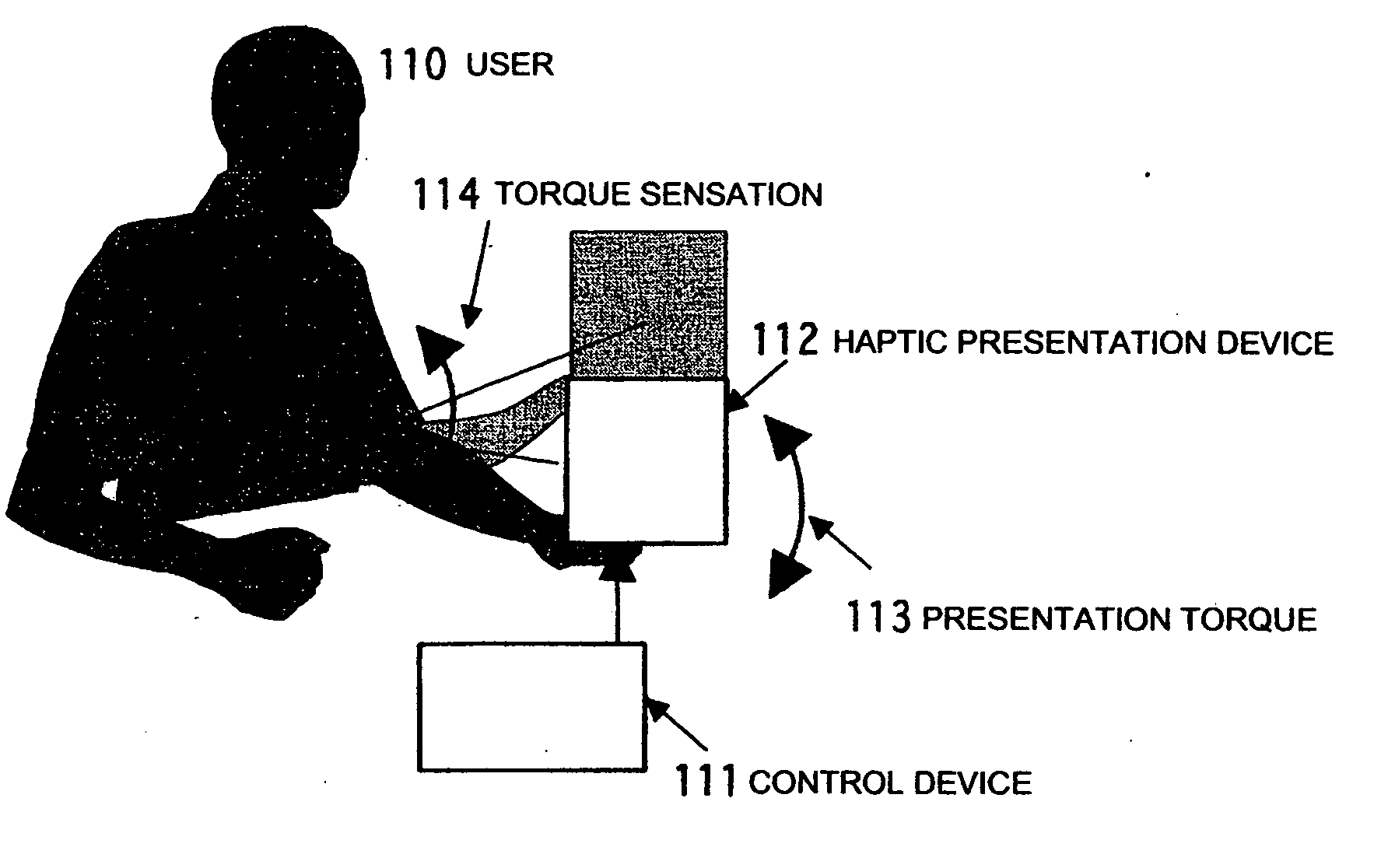
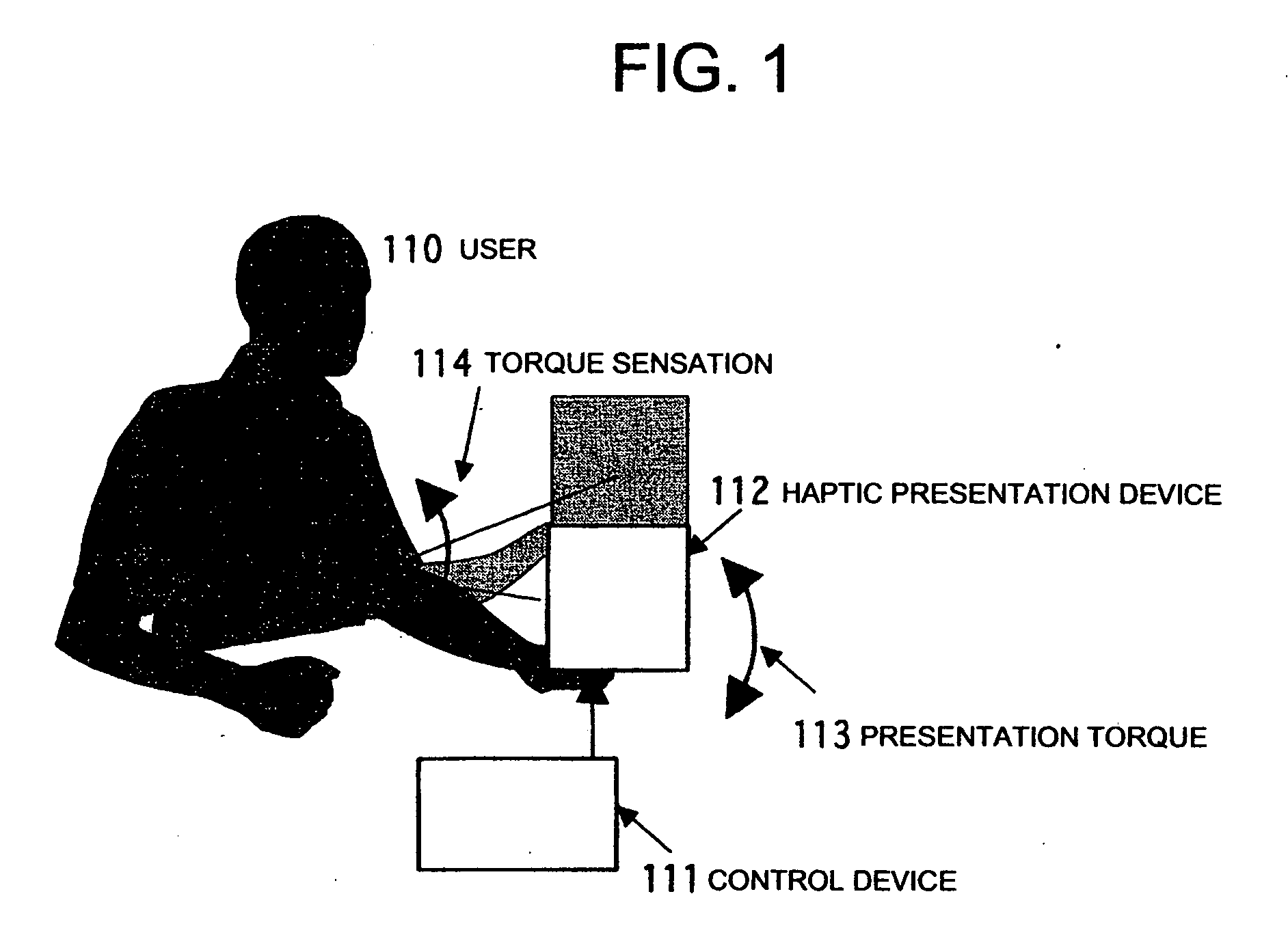
A system and a method are realized in which in a conventional non-grounding man-machine interface having no reaction base on the human body and for giving the existence of a virtual object and the impact force of a collision to a person, a haptic sensation of a torque, a force and the like can be continuously presented in the same direction, which can not be presented by only the physical characteristic of a haptic sensation presentation device. In a haptic presentation device 112, the rotation velocity of at least one rotator in the haptic presentation device 112 is controlled by a control device 111, and a vibration, a force or a torque as the physical characteristic is controlled, so that the user 110 is made to conceive various haptic information of the vibration, force, torque or the like. The haptic information presentation system uses a human sensory characteristic or illusion to suitably control the physical quantity, and causes the person to feel a force which can not exist physically, or a haptic sensory physical characteristic.

Description

TECHNICAL FIELD [0001] The present invention relates to a haptic information presentation system and method, which uses sensory characteristics. [0002] More particularly, the invention relates to a haptic information presentation system, a haptic information presentation method, a haptic presentation device of a haptic information presentation system, and a control device of a haptic information presentation system, which is for providing a man-machine interface mounted on an equipment used in the field of VR (Virtual Reality), an equipment used in the field of game, a cellular phone, a portable navigation equipment, a PDA (Personal Digital Assistant) or the like. BACKGROUND ART [0003] With respect to a conventional haptic device in the VR, in the haptic presentation of a tensile force or reaction force, a haptic presentation part in contact with a human sense organ and a haptic presentation system main body are connected to each other by a wire or an arm, and there has been a disad...

Claims


Application Information

Patent Timeline
Patent Type & Authority Applications(United States)
IPC IPC(8): G09G5/00G06F3/00G06F3/01G10K15/04
CPCG06F3/016G10K15/04G08B6/00H04B3/36G06F3/014B06B1/045G05D19/02B06B1/04G06F3/017G06F3/041G09G5/00G06F3/011G06T19/006A63F13/285G06F2203/013
Inventor NAKAMURA, NORIOFUKUI, YUKIOSAKAI, MASATAKA
Owner NAT INST OF ADVANCED IND SCI & TECH
Why Eureka
Try Eureka