Method and apparatus for controlling bias point of optical transmitter

Inactive Publication Date: 2007-04-26
FUJITSU LTD
View PDF5 Cites 16 Cited by
  • Summary
  • Abstract
  • Description
  • Claims
  • Application Information

AI Technical Summary

Benefits of technology

[0014] It is an object of the present invention to at l

Problems solved by technology

However, according to the optical transmitters described in the above documents, the amplitude and the bias point need to be set while monitoring the waveform each time when an optical signal is transmitted, which is troublesome for the user.
Furthermore, the conventional optical transmitter cannot adjust the bias point app

Method used


Image

  • Method and apparatus for controlling bias point of optical transmitter
  • Method and apparatus for controlling bias point of optical transmitter
  • Method and apparatus for controlling bias point of optical transmitter

Examples


second embodiment

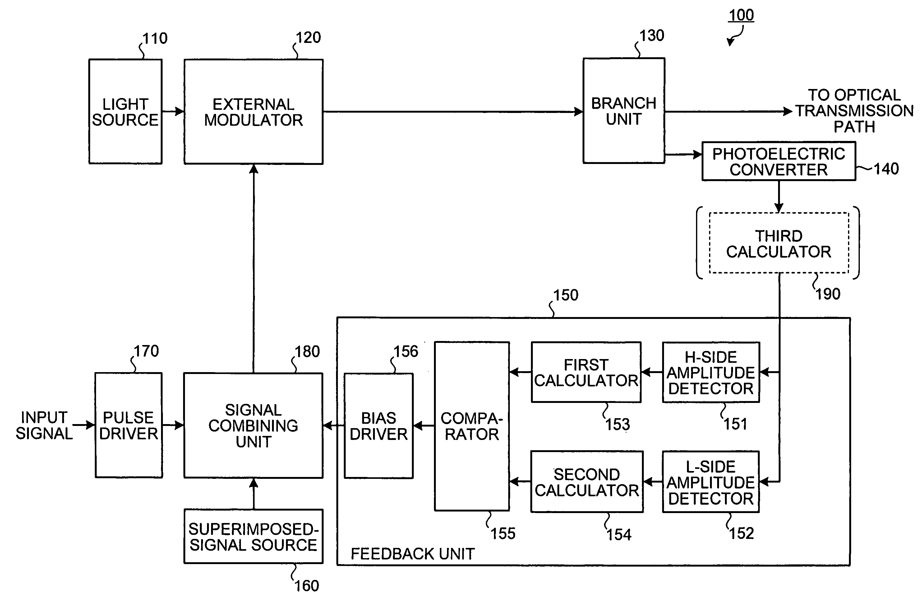
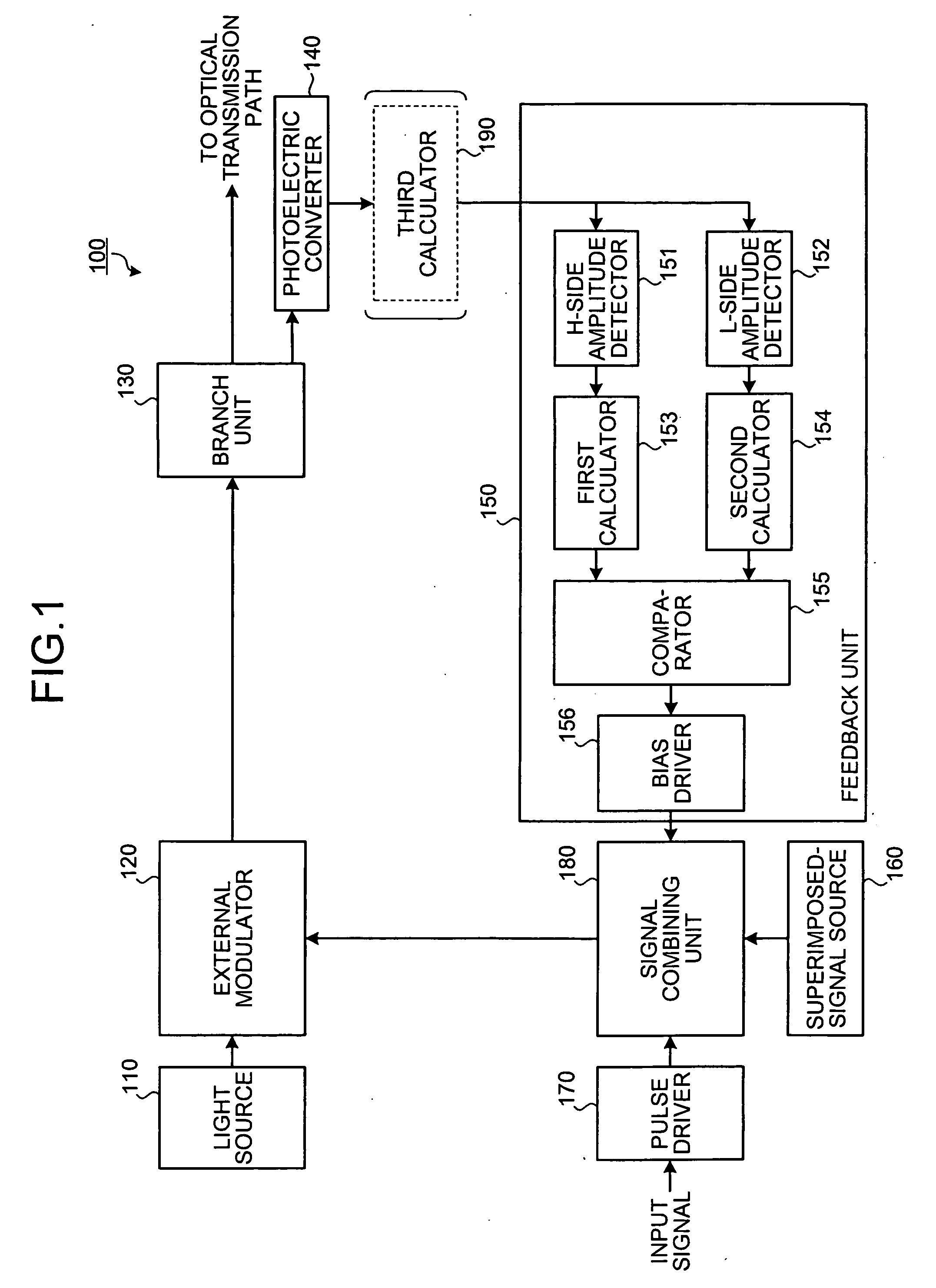
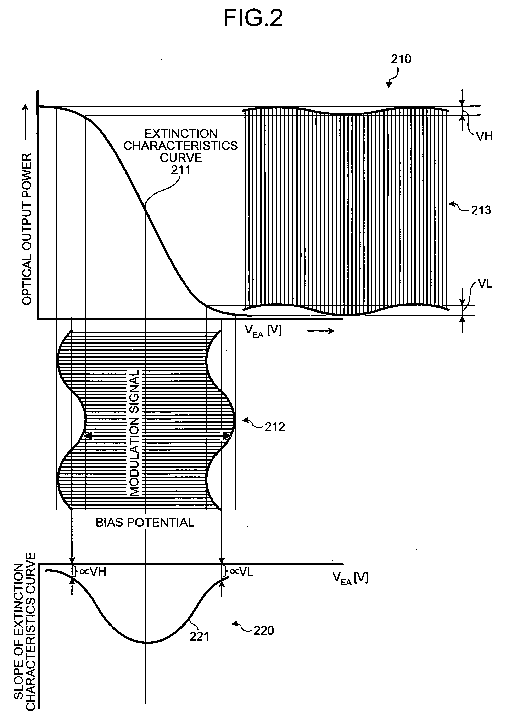
[0043] A procedure of a bias point control according to the present invention is explained next with reference to FIGS. 4 and 5. The bias point control can be widely applied to modulators having different extinction characteristics from that shown in FIG. 2, that is, point-asymmetrical extinction characteristics shown in FIG. 4. A horizontal axis of a graph 410 represents a voltage VEA (V) of an electric signal input to the external modulator 120, and a vertical axis of the graph 410 represents optical output power of an optical signal output from the external modulator 120. A curve 411 represents extinction characteristics of the external modulator 120. A horizontal axis of a graph 420 represents the voltage VEA (V) of the electric signal input to the external modulator 120, and a vertical axis of the graph 420 represents a slope of the curve 411.

[0044] When a modulation signal 412 is input to the external modulator 120, the external modulator 120 outputs an optical signal 413. The...

third embodiment

[0053] A procedure of a bias point control according to the present invention is explained next with reference to FIG. 6. The bias point control can be widely applied to modulators having point-symmetric extinction characteristics as shown in FIG. 2, to minimize the sum of the variation widths VH and VL.

[0054]FIG. 6 is a flowchart of the bias control according to the third embodiment. A reference potential V2 for the comparator 155 is set to 0, and a variable S is set to 1 (step S601). The bias driver 156 sets the EA bias as the initial bias point (step S602). A superimposed signal from the superimposed-signal source 160 and a modulation pulse from the pulse driver 170 are input to the signal combining unit 180 (step S603). The light source 110 inputs light to the external modulator 120 (step S604). The photoelectric converter 140 converts the light output from the external modulator 120 into an electric signal (step S605).

[0055] The H-side amplitude detector 151 detects the variat...


PUM


Abstract

An optical transmitter includes: a modulating unit that modulates an optical signal based on an electric signal; a first detecting unit that detects a first variation width of a maximum output of the modulated optical signal; a second detecting unit that detects a second variation width of a minimum output of the modulated optical signal; a comparing unit that performs a comparison of the first variation width and the second variation width; and an adjusting unit that adjusts a bias potential of the electric signal based on a result of the comparison.

Description

CROSS-REFERENCE TO RELATED APPLICATIONS [0001] This application is based upon and claims the benefit of priority from the prior Japanese Patent Application No. 2005-307420, filed on Oct. 21, 2005, the entire contents of which are incorporated herein by reference. BACKGROUND OF THE INVENTION [0002] 1. Field of the Invention [0003] The present invention relates to a technology for controlling the bias point of an optical transmitter automatically. [0004] 2. Description of the Related Art [0005] A conventional optical transmitter for an optical communication system uses a modulation system, such as a direct modulation system, an internal modulation system, and an external modulation system, which is suitable for a type of a light source and a communication speed. In recent years, the external modulation system having a small variation in the wavelength of an optical signal (that is, a chirping) regardless of a transmission speed calls attention, and has been widely used. [0006]FIG. 8 i...

Claims


Application Information

Patent Timeline
IPC IPC(8): H04B10/04
CPCH04B10/505H04B10/50575H04B10/564
Inventor SHIMIZU, KAZUYOSHINAGAYAMA, AKIRA
Owner FUJITSU LTD
Why Eureka
Try Eureka