Inlet device and a method of controlling the introduction of a fluid into a separator

a technology of separator and fluid, which is applied in the direction of sedimentation regulating devices, centrifugal force sediment separation, auxillary pretreatment, etc., can solve the problems of complex emulsion patterns, complex emulsion patterns, and new challenges for oil companies in their separation process

Inactive Publication Date: 2007-05-03
SULZER MANAGEMENT AG
View PDF6 Cites 55 Cited by
  • Summary
  • Abstract
  • Description
  • Claims
  • Application Information

AI Technical Summary

Benefits of technology

[0009] One object of the invention is to provide a device and a method by means of which

Problems solved by technology

Recently, some oil companies experience new challenges for their separation process.
The fact that some of the wells are oil continuous and some are water continuous may cause complex emulsion patterns.
This adds to the complexity of the incoming gas/oil/water

Method used


Image

  • Inlet device and a method of controlling the introduction of a fluid into a separator
  • Inlet device and a method of controlling the introduction of a fluid into a separator
  • Inlet device and a method of controlling the introduction of a fluid into a separator

Examples


Embodiment Construction

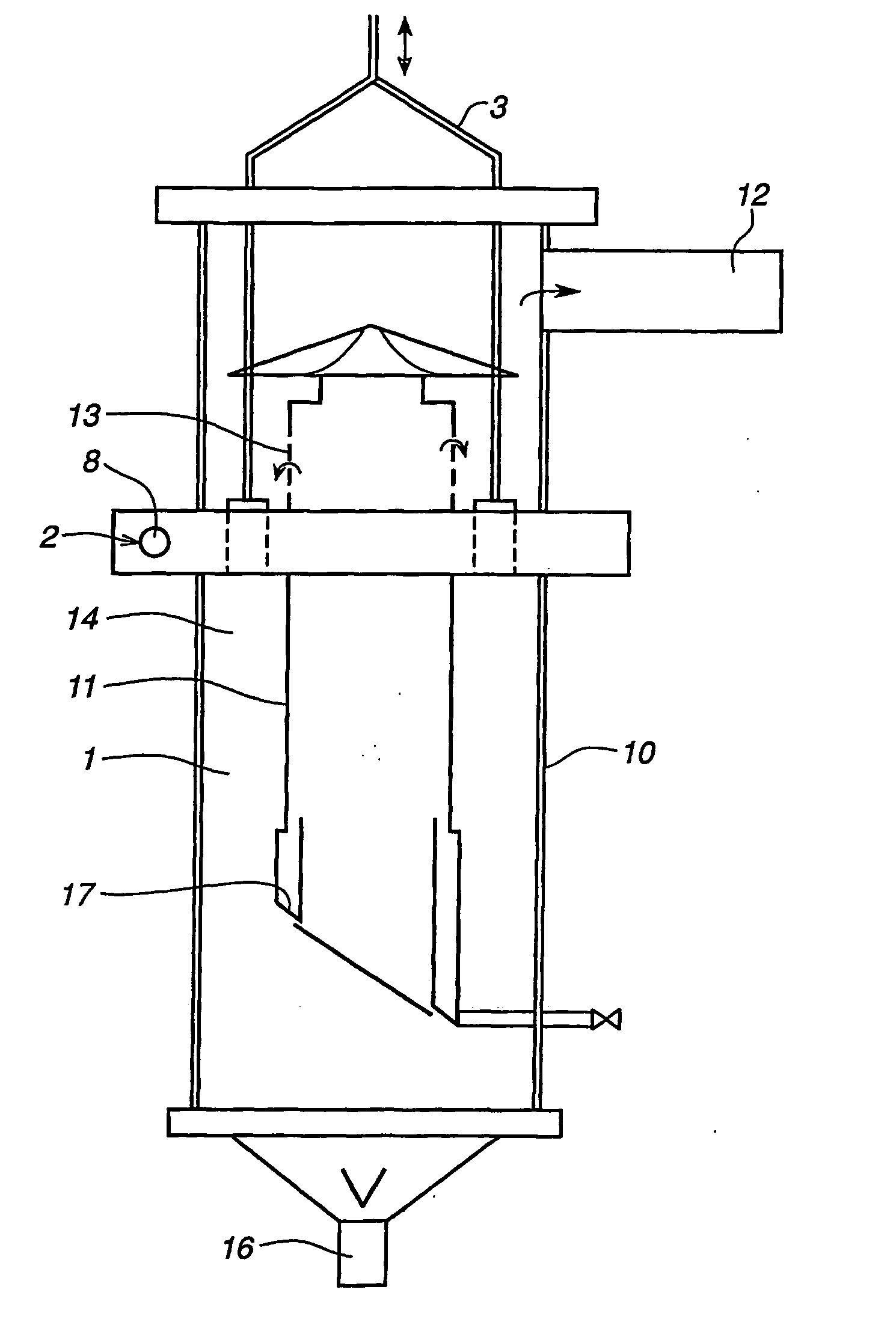
[0043]FIG. 1 shows a separator 1 provided with an inlet device 2 according to one embodiment of the invention. The separator 1 defines a multiphase cyclone of the kind as described in e.g. the Norwegian patent no. 315640 for separation of gas, liquid, and solid particles.

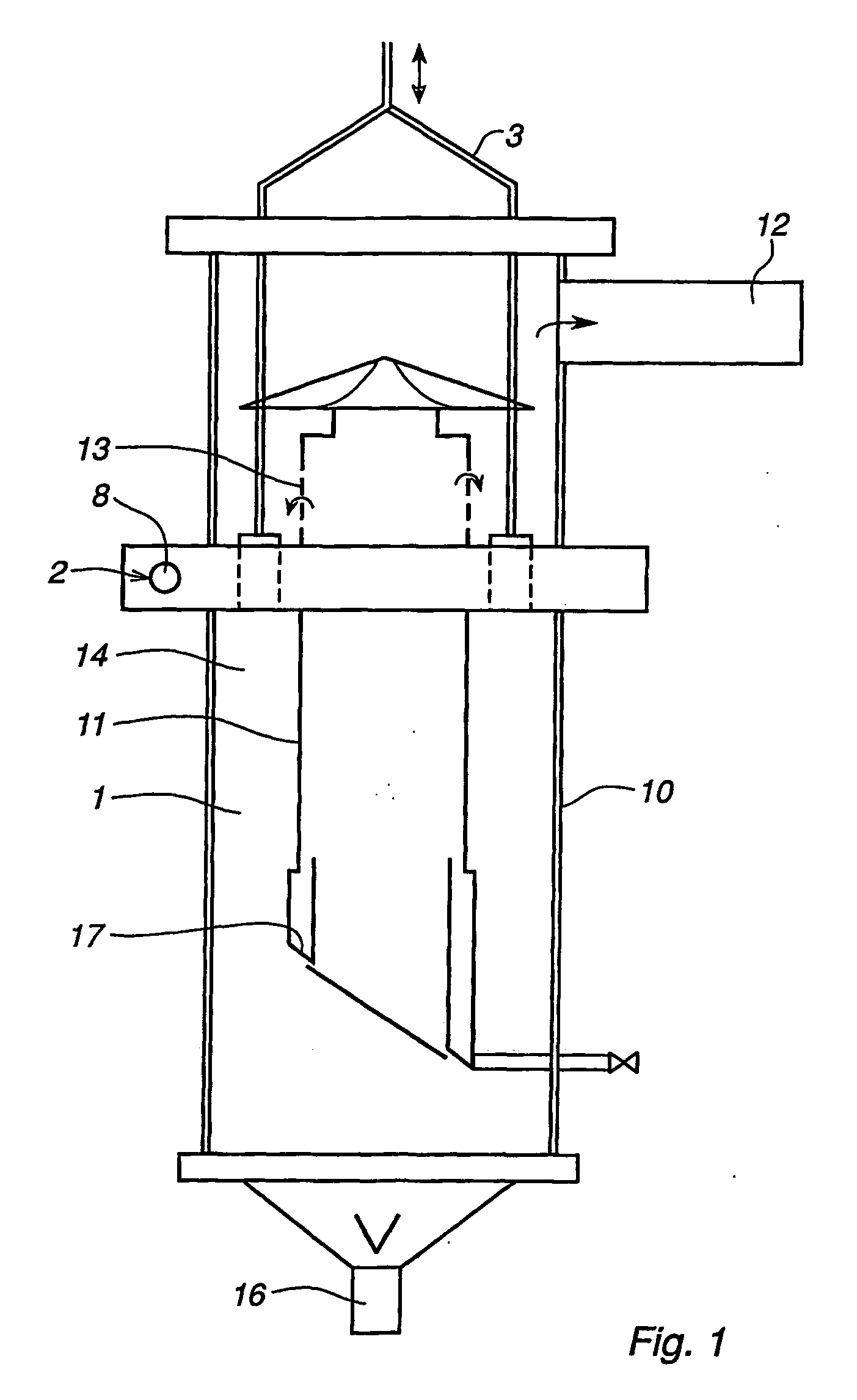
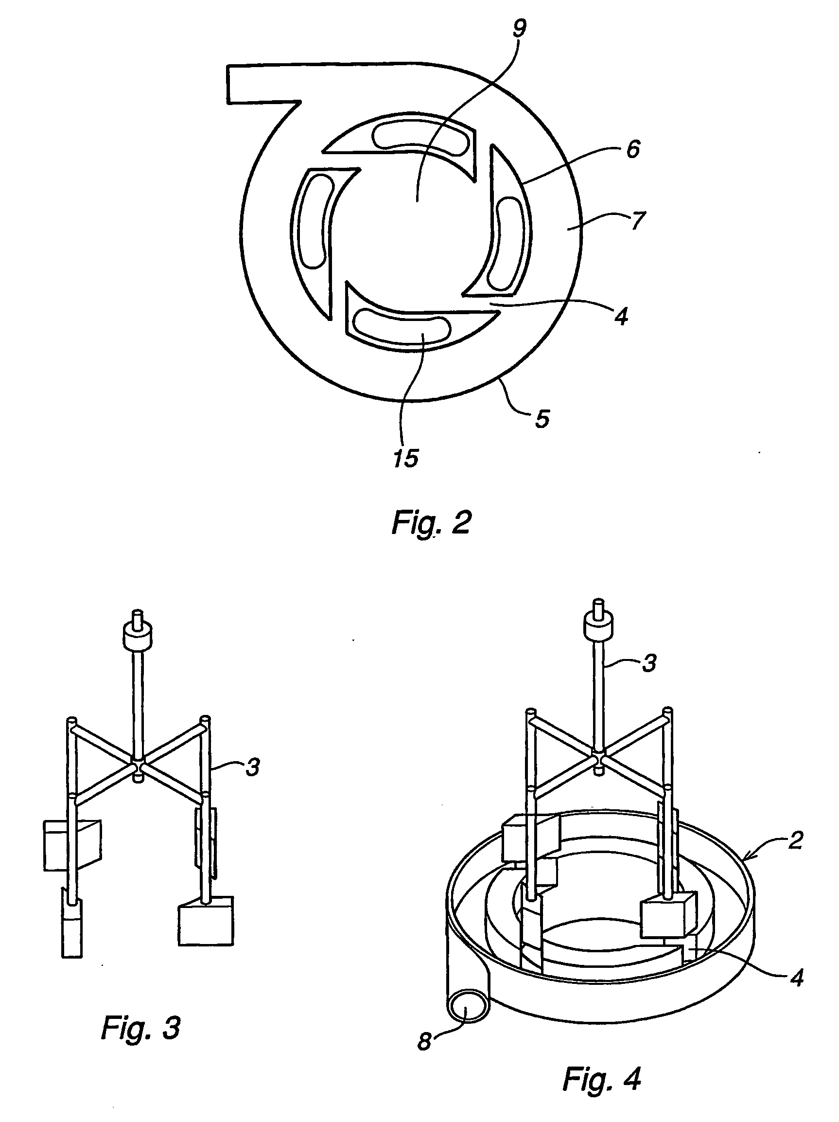
[0044]FIG. 2 shows an inlet device according to prior art that might be arranged in the cyclone 1, while FIGS. 3 and 4 show a further development of the inlet device 2 in accordance with a first preferred embodiment of the invention. The inlet device 2 according to FIGS. 1 to 4 differs from the prior art inlet device in that it comprises means 3 for controllable closure of communication channels 4 in the inlet device. The prior art inlet device of FIG. 2 could here be regarded as a part of the inlet device according to this embodiment of the invention.

[0045] The inlet device 2 comprises a generally cylindrical outer wall 5 and a generally cylindrical inner wall 6, the outer and inner wall 5, 6 defining at least a ...


PUM

PropertyMeasurementUnit
Timeaaaaaaaaaa
Flow rateaaaaaaaaaa
Areaaaaaaaaaaa

Abstract

An inlet device to a separator including a generally tubular outer wall and a generally tubular inner wall. The walls define at least a part of a first annular path between them. An inlet opening provides for the passage of a fluid through the outer wall into the first annular path. At least one communication channel provides for the passage of a fluid from the first annular path into the second annular path. At least one movable closing element provides for at least partial closure of the fluid passage from the first path into the second path. The communication channel(s) is/are arranged to extend along the outside of the inner wall downwards from the first path into the second path, wherein the second path is arranged below the first path.

Description

TECHNICAL FIELD [0001] The present invention relates to an inlet device to a separator, said device comprising: a generally tubular outer wall and a generally tubular inner wall, said outer and inner wall defining at least a part of a first annular path between them, and an inlet opening through the outer wall into the first annular path for the at least one passage of a fluid from the first annular path into a second annular path inside the inner tubular wall or from the first annular path along the outside of the inner tubular wall downwards into the second annular path, said fluid comprising two or more phases being subjected to separation. [0002] The invention also relates to a method of controlling the introduction of a fluid into a separator, preferably a cyclone separator, in which the fluid is introduced, under tangential g-force-generating movement thereof into a second annular path via an inlet opening through an outer tubular wall and a first annular path between the oute...

Claims


Application Information

Patent Timeline
IPC IPC(8): B01D45/00B01D17/00B01D19/00B04CB04C5/04B04C5/103B04C11/00
CPCB01D17/00B01D19/0057B04C5/04B04C5/103B04C11/00B04C2003/006B01D17/0208B01D17/0211B01D17/0217B01D21/0024B01D21/2411B01D21/245B01D21/26B01D21/267B01D21/34B01D2221/04B04C3/06
Inventor NILSEN, PAL JAHREMICHAELSEN, JARLEBALK, IVAR
Owner SULZER MANAGEMENT AG
Why Eureka
Try Eureka