Methods and apparatus for reducing stress variations in glass sheets produced from a glass ribbon

a technology of stress variation and glass ribbon, which is applied in the field of glass ribbon manufacturing, can solve the problems of substantial number of defective (rejected) displays, changes in the vacuumed-flat shape of glass sub-pieces,

Inactive Publication Date: 2007-05-03
CORNING INC
View PDF0 Cites 40 Cited by
  • Summary
  • Abstract
  • Description
  • Claims
  • Application Information

AI Technical Summary

Benefits of technology

[0010] In certain preferred embodiments of the invention, step (c) reduces movement in a horizontal direction of at least a portion of the ribbon's central region (51), said portion being located between the forming assembly (41) and the separating assembly (20). In accordance with these embodiments, the temperature of the glass at said portion is preferably within the glass'glass transition temperature range. Although not wishing to be bound by any particular theory of operation, it is believed that in this way, variations in the stress levels of glass sheets (11) cut from the ribbon (13) are reduced at at least one location, e.g., along at least one edge of the glass sheet (11).

Problems solved by technology

Such stress relief in general results in changes in the vacuumed-flat shape of the glass sub-pieces, a phenomenon referred to by display manufacturers as “distortion.” Although the amount of shape change is typically quite small, in view of the pixel structures used in modern displays, the distortion resulting from cutting can be large enough to lead to substantial numbers of defective (rejected) displays.
Accordingly, the distortion problem is of substantial concern to display manufacturers and specifications regarding allowable distortion as a result of cutting can be as low as 2 microns or less.

Method used


Image

  • Methods and apparatus for reducing stress variations in glass sheets produced from a glass ribbon
  • Methods and apparatus for reducing stress variations in glass sheets produced from a glass ribbon
  • Methods and apparatus for reducing stress variations in glass sheets produced from a glass ribbon

Examples


example

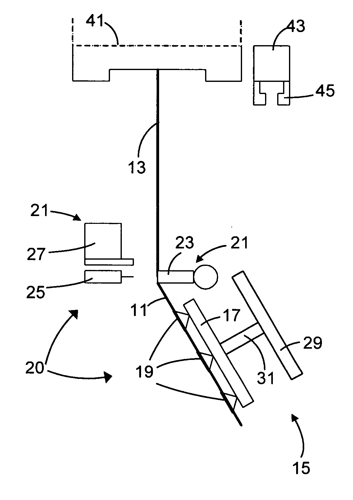
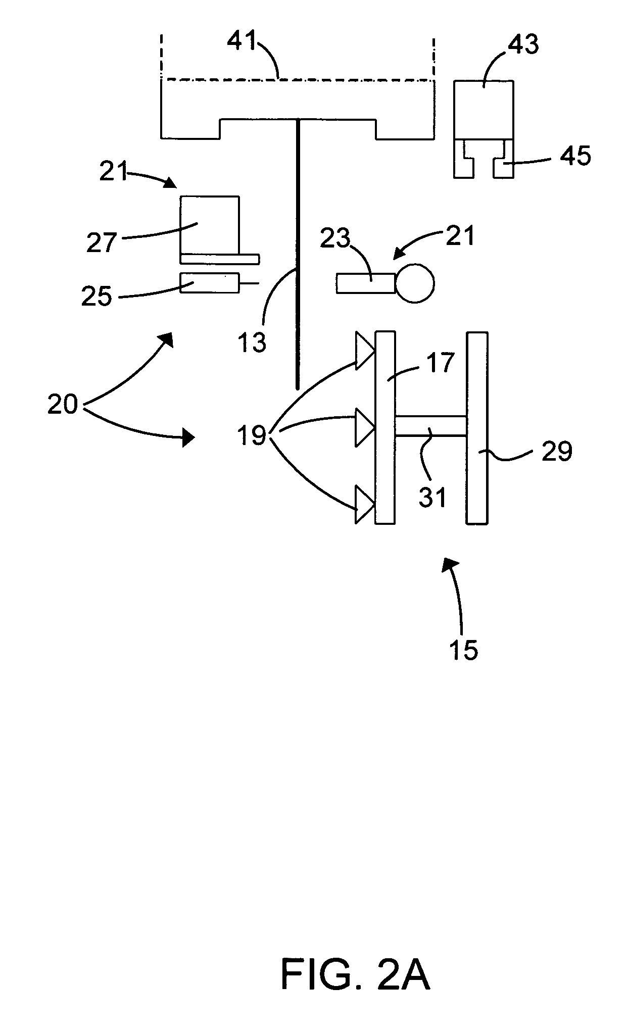
[0094] A ribbon of glass produced by a fusion process and having a thickness of 0.5 mm was manually constrained from movement in a horizontal plane along its edges at a vertical location below the separation line. Stress measurements were made on consecutive samples produced with and without such constraint. In particular, stress measurements were made along the four edges of the sheets.

[0095] The highest variations in stress levels were observed for the edge corresponding to the side of the ribbon closest to the glass inlet to the isopipe used to produce the ribbon. Those stress levels are shown in FIG. 7A for the unconstrained case. FIG. 7B shows the results for the same edge when constrained as described above. The significant reductions in the variations in stress levels are evident. Reductions in stress variations were also seen for the other three edges, but since the levels of stress for the unconstrained condition were lower, the reductions achieved by constraining horizont...


PUM

PropertyMeasurementUnit
lengthaaaaaaaaaa
thicknessaaaaaaaaaa
lengthsaaaaaaaaaa

Abstract

Apparatus and methods are provided for reducing the variability of stress levels in glass sheets (11) cut from a moving glass ribbon (13). The reductions in variability are achieved by constraining the edge regions (53,55) of the ribbon (13) from movement in a horizontal plane at at least one location below the location where a separating assembly (20) forms a separation line (47) in the ribbon (13). Sets of vertically arranged wheels (35) which engage the edge regions (53,55) of the ribbon (13) can be used to provide the horizontal constraint without compromising the central, quality area (51) of the glass ribbon (13).

Description

FIELD OF THE INVENTION [0001] This invention relates to the manufacture of glass sheets such as the glass sheets used as substrates in display devices such as liquid crystal displays (LCDs). More particularly, the invention relates to methods for reducing the amount of distortion which glass substrates exhibit when cut into parts during, for example, the manufacture of such displays. BACKGROUND OF THE INVENTION [0002] Display devices are used in a variety of applications. For example, thin film transistor liquid crystal displays (TFT-LCDs) are used in notebook computers, flat panel desktop monitors, LCD televisions, and Internet and communication devices, to name only a few. [0003] Many display devices, such as TFT-LCD panels and organic light-emitting diode (OLED) panels, are made directly on flat glass sheets (glass substrates). To increase production rates and reduce costs, a typical panel manufacturing process simultaneously produces multiple panels on a single substrate or a su...

Claims


Application Information

Patent Timeline
Patent Type & Authority Applications(United States)
IPC IPC(8): C03B37/02C03B37/025F27B7/33
CPCC03B17/068Y02P40/57C03B33/023C03B33/03C03B35/16C03B35/20
Inventor KIRBY, THOMAS EDWARDMARKHAM, SHAWN RACHELLE
Owner CORNING INC
Why Eureka
Try Eureka