Apparatus for rotation of a large body about an axis

a technology for rotating bodies and axes, which is applied in the direction of machine supports, manufacturing tools, lighting and heating apparatus, etc., can solve the problems of increasing the cost of electric or hydraulic motors, increasing the cost of drive systems, so as to achieve less cost and more reliability.

Inactive Publication Date: 2007-05-03
KANEFF STEPHEN
View PDF9 Cites 36 Cited by
  • Summary
  • Abstract
  • Description
  • Claims
  • Application Information

AI Technical Summary

Benefits of technology

[0012] It is an object of the present invention to provide a new mechanism for rotating a large body about an axis, which is suitable for use with large dish antennae, and which (a) is both less costly and more reliable than either the conventional motor and pinion arrangement or the mechanism described above in which the end of a rod is moved from one anchor member to an adjacent anchor member, and (b) is also suitable for the rotation of other large bodies.

Problems solved by technology

The electric or hydraulic motor required to rotate large bodies, and the reduction gearbox, are expensive components.
However, in the case of movement of the antenna by a motor and pinion drive, transients of high energy demand occur during the continual starting and stopping of the motor.
This, in turn, makes the drive system even more expensive and potentially more prone to maintenance demands.
An “off-steering” device requires a back-up power supply, typically a bank of batteries which require regular maintenance, and this adds to the cost of the tracking equipment.
However, it does have some disadvantages, including the fact that the anchor members, which have to be substantially equi-spaced on a platform, must be mounted with care, to ensure that the end of the ram rod is successfully transferred to an adjacent anchor member every time such movement is required.
This problem is accentuated if fewer anchor members are used, with the consequential need for rams of longer stroke or “throw”.
Even with careful mounting of the anchor members, a number of operational conditions and factors can combine to cause the engagement of the end of the ram rod with the new anchor member to fail, even when care is taken to calibrate the whole system to more accurately locate the positions of the anchor members in the memory of the control computer, to ease the problem of the rod end failing to locate and lock onto the next anchor member.
Techniques that may be employed to avoid this situation result in an increased cost and complexity of the system.
The increased complexity means that more maintenance is likely to be required.
Also, in spite of rapid computer control processes, the time taken for the end of the rod to move from a particular anchor member to the adjacent anchor member is significant and can cause a momentary undesirable tracking delay, allowing the receiver to lag slightly behind the sun.
This problem can be ameliorated by deliberately causing the dish structure to move slightly ahead of its required position just before the changeover manoeuvre commences, but this requires extra tracking energy.

Method used


Image

  • Apparatus for rotation of a large body about an axis
  • Apparatus for rotation of a large body about an axis
  • Apparatus for rotation of a large body about an axis

Examples


Embodiment Construction

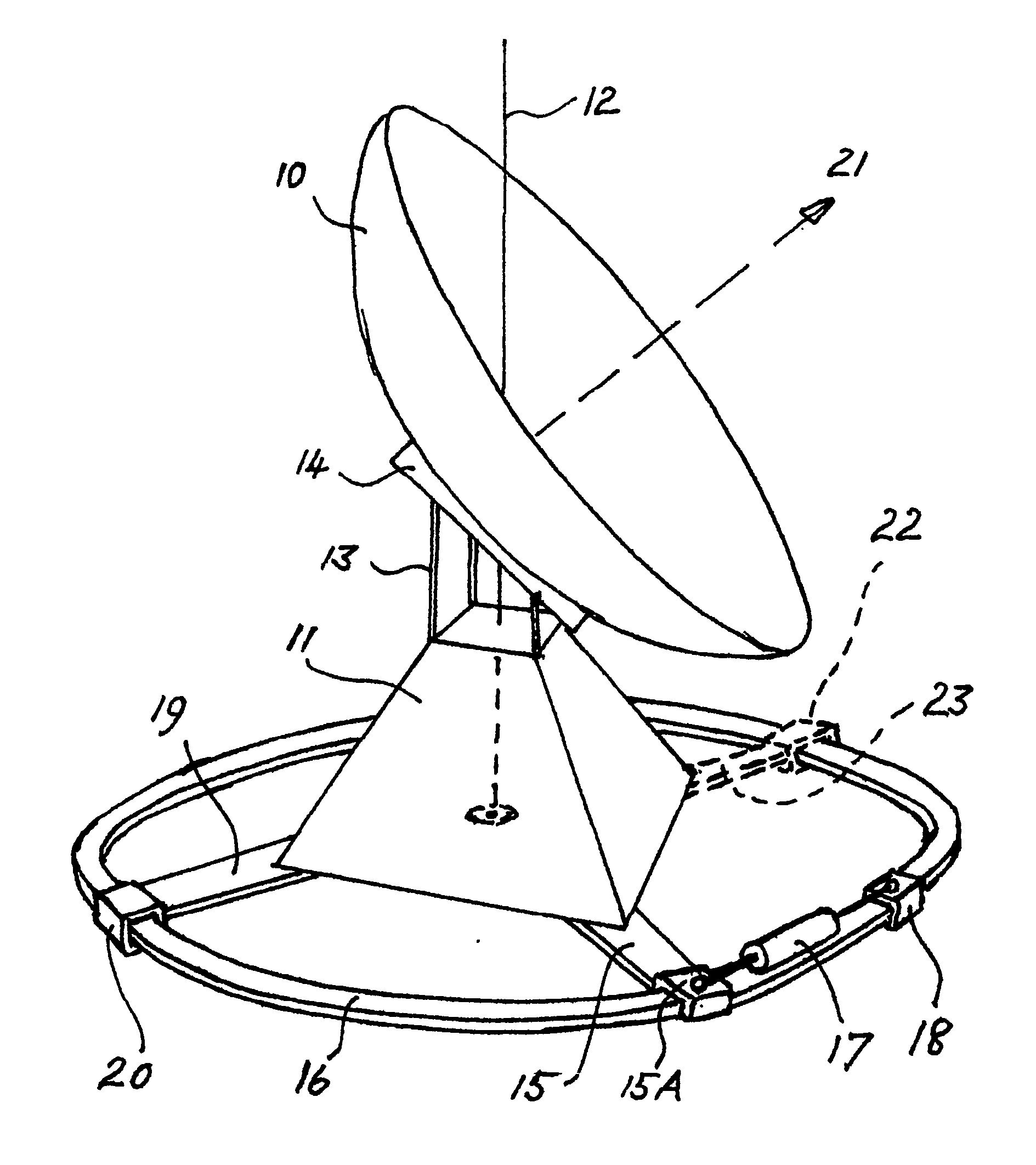
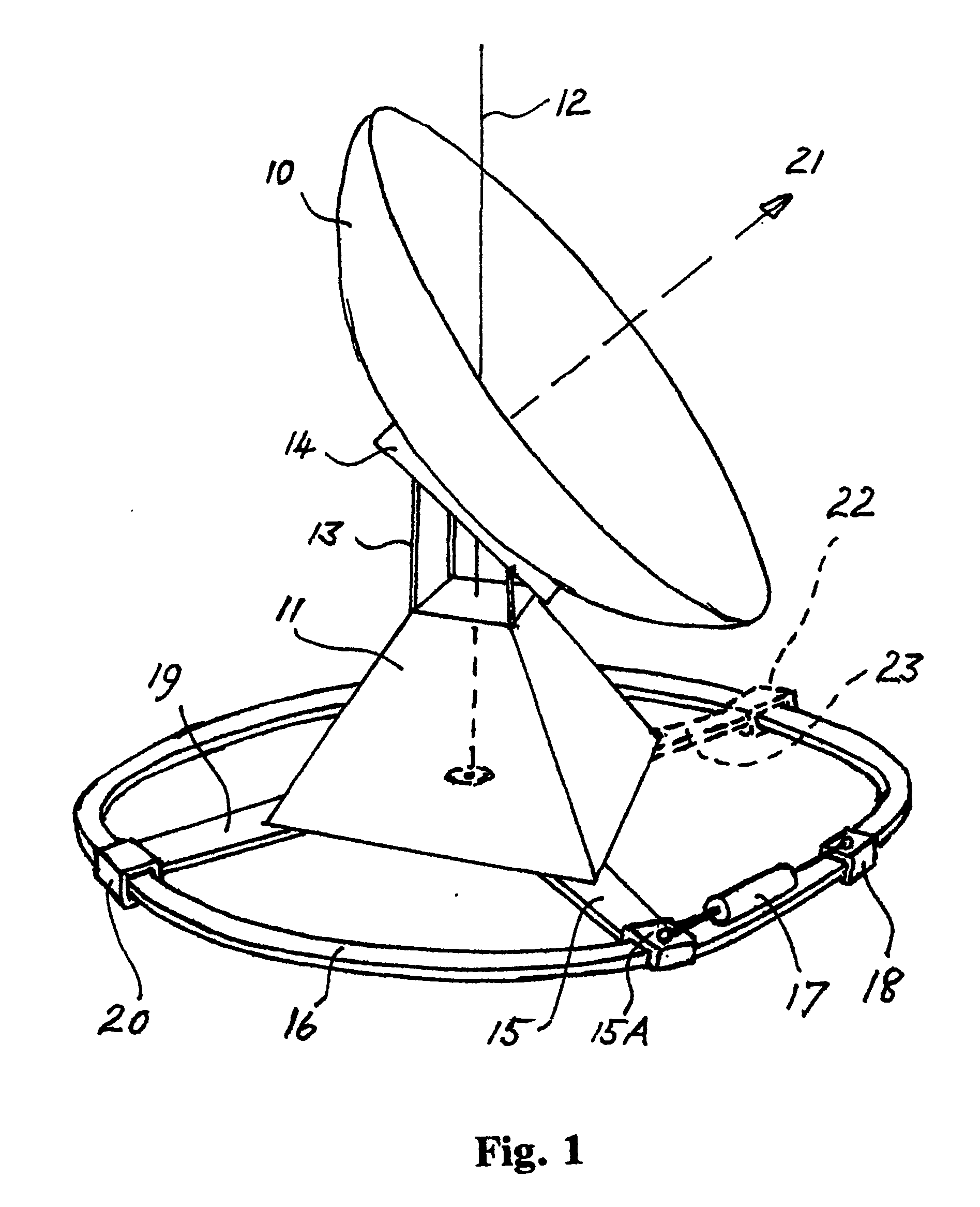
[0034]FIGS. 1 and 2 each show, schematically, a dish antenna to be rotated about a vertical axis 12. The dish antenna for which the present invention was developed is a large solar energy collector which has been assembled at The Australian National University, in Canberra, Australia. That solar energy collector has been described in the specifications of, inter alia, Australian patents Nos. 677,257 and 700,607 and U.S. Pat. Nos. 5,757,335 and 5,934,271. However, it is emphasised that the solar energy collector and the dish antennae featured in FIGS. 1 and 2 are only examples of a rotatable structure with which the present invention may be used, and the present invention is not limited in its application to solar energy collectors generally, or to rotatable antennae.

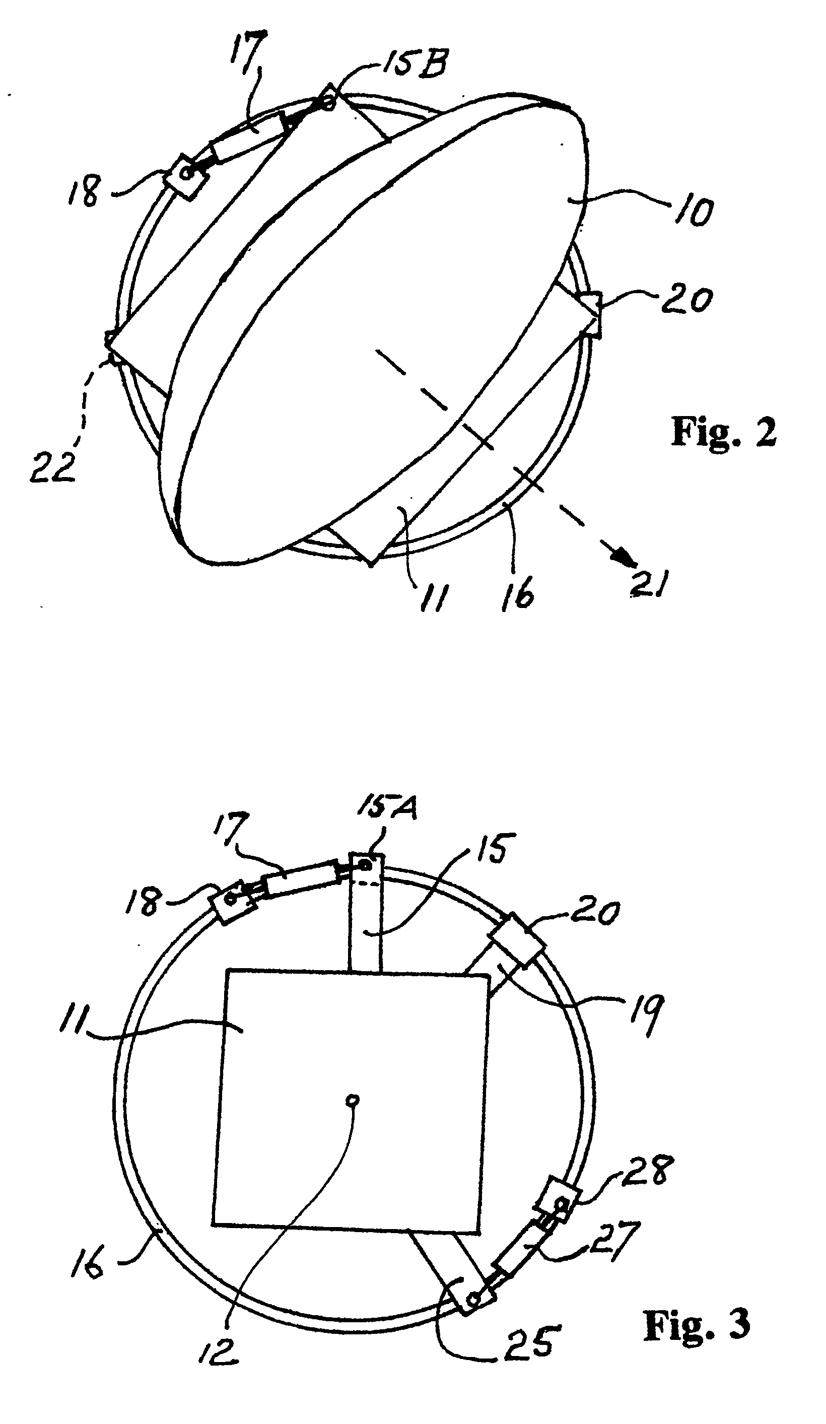
[0035] The antennae illustrated in FIGS. 1 and 2 each have a dish 10 supported on a base frame 11. The support of the dish on the base frame is shown schematically in FIG. 1 by columns 13 and a support unit 14. The supp...


PUM


Abstract

Apparatus for the rotation of a large body, such as the base frame (11) of a solar energy collector having a large reflective dish (10), about an axis (12) utilizes a ring member or arcuate member (16). An actuator clamp (18) can be moved along the ring or arcuate member when it is not clamped to it. The actuator clamp is connected to one end of an expansion and contraction device, such as a hydraulic ram (17). The other end of the ram is connected to the body or to a rigid arm (15) that is securely connected to the body. With the actuator clamp firmly clamped to the ring or arcuate member, the expansion or contraction of the ram causes the body to rotate about axis. At least one auxiliary clamp (20, 22) may be provided which may be used to continue the movement of the body while the position of the actuator clamp on the ring or arcuate member is changed.

Description

TECHNICAL FIELD [0001] This invention concerns the rotation of a body about an axis. More particularly, it concerns the controlled rotation (which includes partial rotation) of a large body about an axis, and linear movement of a large body. [0002] This invention was developed to provide effective actuation and control of the rotation of structures on which are mounted large dish antennae, such as the dish antennae used in radio telescopes, solar energy collectors and satellite communication systems, and in particular the large solar energy collector dish antennae described in the specifications of Australian patents Nos. 677,257 and 700,607, and U.S. Pat. Nos. 5,757,335 and 5,934,271. For this reason, the large dish antenna application of the invention will be featured in this specification. However, it should be appreciated that the present invention is not limited in its application to the rotation of such structures. [0003] It should also be appreciated that the present inventio...

Claims


Application Information

Patent Timeline
Patent Type & Authority Applications(United States)
IPC IPC(8): H01Q1/12F15B15/02B25B5/00F15B15/06F16B2/12F16M11/08F16M11/18F24J2/54F24S23/71
CPCF16B2/12F16M11/08F16M11/18F16M2200/041F24J2/12F24J2/542F24J2002/5437F24J2002/5479H01Q1/12H01Q1/125Y02E10/42Y02E10/47F24S23/71F24S2030/145F24S30/452F24S2030/11Y02E10/40
Inventor KANEFF, STEPHEN
Owner KANEFF STEPHEN
Why Eureka
Try Eureka