
Single-stage power converter with high power factor

a power converter and single-stage technology, applied in power conversion systems, climate sustainability, energy industry, etc., can solve the problems of less than 100% efficiency of each stage, and achieve the effects of high power factor, good regulation, and high efficiency

Inactive Publication Date: 2005-03-03
LESEA RONALD A
View PDF6 Cites 25 Cited by
  • Summary
  • Abstract
  • Description
  • Claims
  • Application Information

AI Technical Summary

Benefits of technology

[0006] It is therefore an object of the present invention to provide a power supply that is efficient.
[0007] It is another object of the present invention to provide a power conversion product with good output regulation and high input power factor.
[0011] Another advantage of the present invention is that a power supply and method are provided for good regulation and high power factor in the conversion of AC power to DC power.
[0012] Another advantage of the present invention is that a power supply and method are provided that uses fewer power components and therefore can be less costly and more reliable.

Problems solved by technology

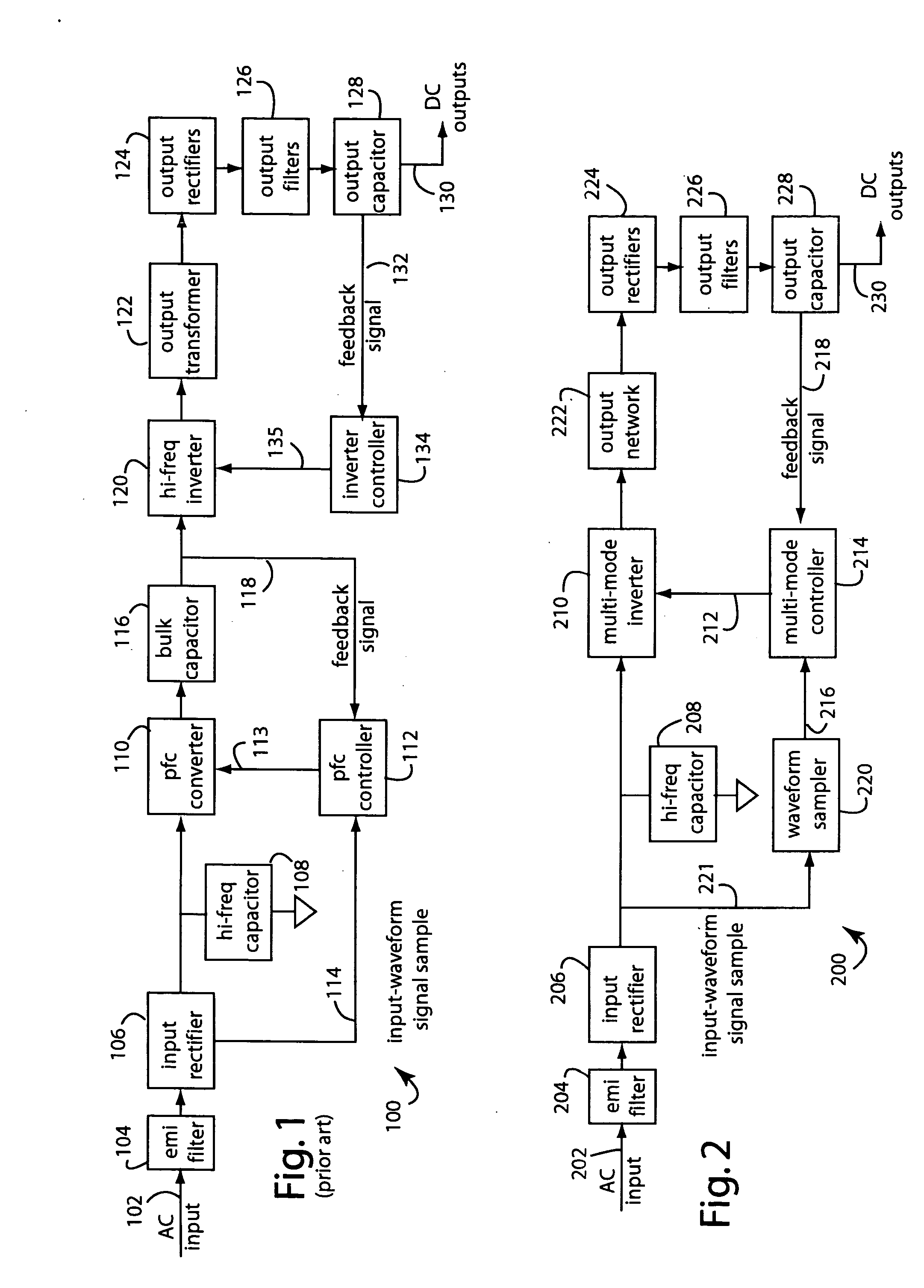
The problem with prior art devices like power supply 100 is there are two stages, each of which is less than 100% efficient.

Method used


Image

  • Single-stage power converter with high power factor
  • Single-stage power converter with high power factor
  • Single-stage power converter with high power factor

Examples


Embodiment Construction

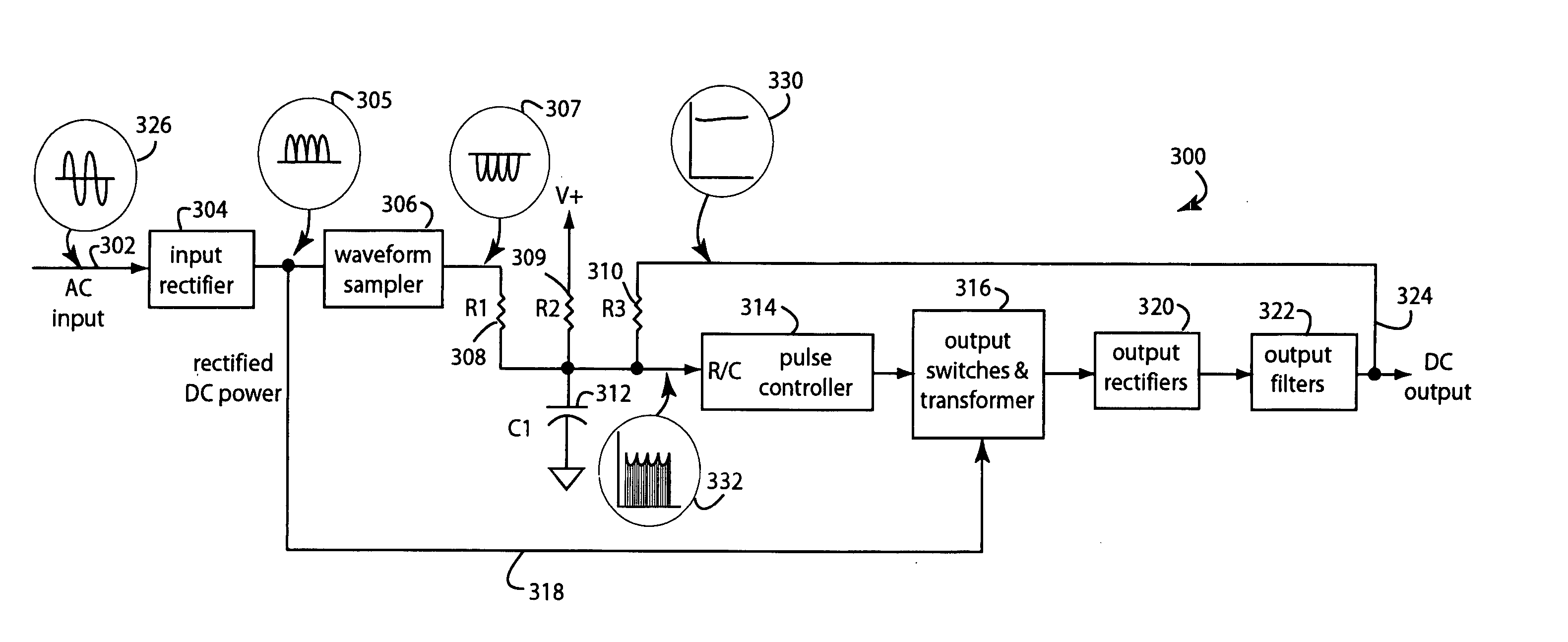
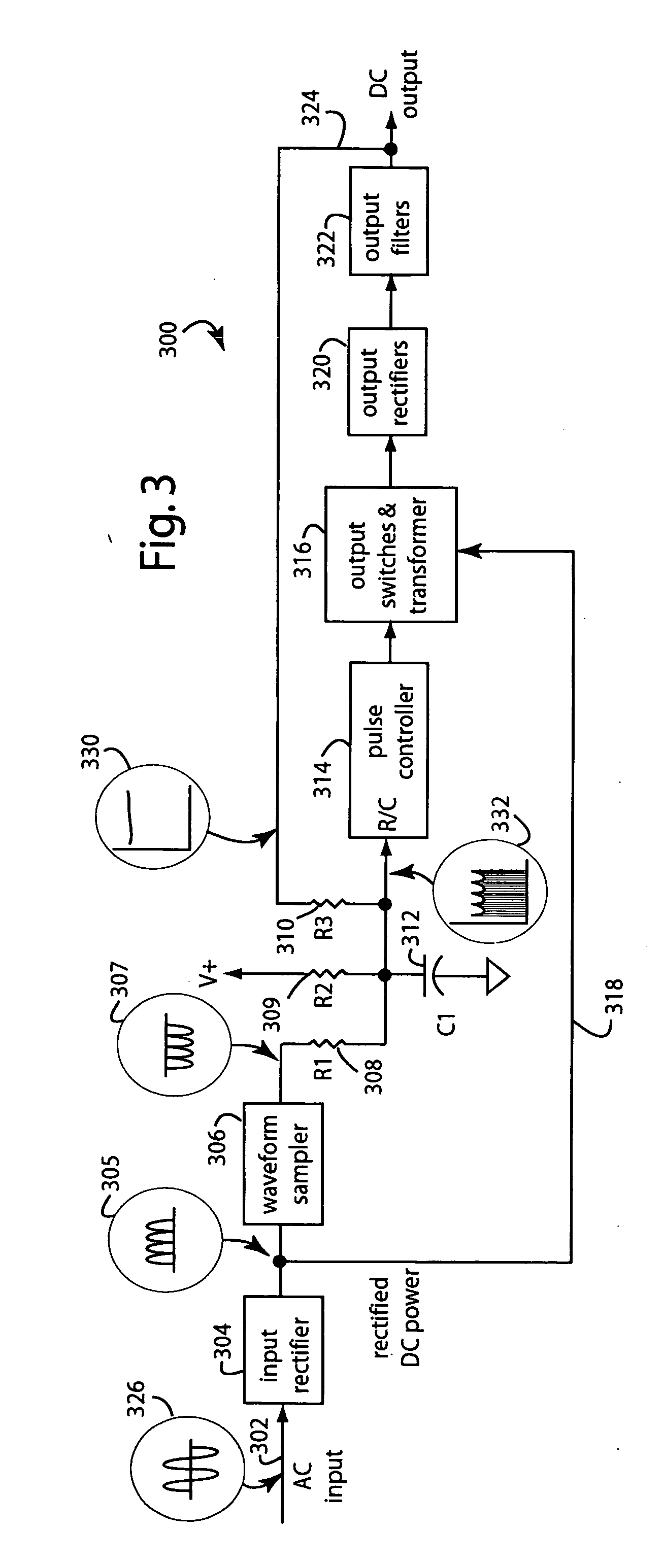
[0017]FIG. 2 represents a power supply embodiment of the present invention, and is referred to herein by the general reference numeral 200. An AC input power 202 is brought in through an electro-magnetic interference (EMI) filter 204 and converted to DC by an input rectifier 206. A high-frequency capacitor 208 filters the raw DC for a multi-mode inverter 210. A voltage-controlled frequency generator can be used to implement multi-mode inverter 210. A single controller signal 212 from a multi-mode controller 214 simultaneously provides for output-voltage regulation and input power-factor correction. This single controller signal 212 is synthesized from both an input sample 216 and an output feedback signal 218. A waveform function 220 operates as a sampler and conditions a signal 221 received from the input rectifier 206. The inverter 210 drives an output network 222, e.g., in a switched-mode type of configuration involving switches to chop the incoming DC, step those through a trans...


PUM


Abstract

A power supply samples a rectified AC-input waveform and a regulated output voltage and combines them to control an AC-to-DC converter. The operating frequency and / or pulse width modulation of a switched-mode power supply are in large part fixed by a highly filtered output feedback signal to maintain a desired output voltage. A sample taken from the AC-input rectifiers is used in another feedback control signal to drive the operating frequency and / or pulse width modulation slightly up and down as a function of the rise and fall of each rectified-waveform sinusoid. The power delivered to the output, and thus the power demand on the input rise and fall with the instantaneous voltage of the AC input sinusoid. So the power factor is controlled by drawing current in-step with the voltage waveform.

Description

1. FIELD OF THE INVENTION [0001] The present invention relates to methods and devices for power conversion, and in particular to single-stage AC to DC power converters that correct power factor and regulate output voltage, output current, or output power in a single stage and with high efficiency. 2. DESCRIPTION OF THE PRIOR ART [0002] Where input power factor correction is required, battery chargers, power supplies, and other alternating current (AC) to direct current (DC) power converters commonly correct input power factor in one stage and then do conversion and regulation of the output in a second stage. If each stage is 80% efficient, then the two-stage efficiency is only 80%×80%, or 64%. [0003]FIG. 1 represents a prior-art two-stage power supply 100. An AC input power 102 is brought in through an electromagnetic interference (EMI) filter 104 and converted to DC by an input rectifier 106. A high-frequency capacitor 108 serves as a low impedance for the high frequency current pu...

Claims


Application Information

Patent Timeline
Patent Type & Authority Applications(United States)
IPC IPC(8): H02M1/00H02M1/42
CPCY02B70/126H02M1/4208Y02B70/10Y02P80/10
Inventor LESEA, RONALD A.
Owner LESEA RONALD A
Learn More