Reactive stimulation of oil and gas wells

a technology active stimulation, which is applied in the direction of fluid removal, drilling machines and methods, borehole/well accessories, etc., can solve the problems of reducing the efficiency of oil and gas wells, affecting the flow of fluid around the perforation area, so as to enhance the burning of hydrocarbons

Inactive Publication Date: 2007-05-03
BOND LESLEY O
View PDF34 Cites 7 Cited by
  • Summary
  • Abstract
  • Description
  • Claims
  • Application Information

AI Technical Summary

Benefits of technology

[0011] The present invention is directed to apparatus for stimulating production from a hydrocarbon-containing formation in an oil or gas well. The apparatus comprises a container sized to be received and supported in the well at a level adjacent the formation. At least one shaped charge is supported within the container. The shaped charge is adapted, when ignited, to perforate the formation and to initiate a burn of hydrocarbons therein. The apparatus includes a supply of oxygen-rich material supported within the container and adapted to be introduced explosively into the formation with the shaped charge. In this way, the burn of hydrocarbons therein is extendable. The apparatus further includes at least one igniter for detonating the shaped charge.
[0012] Still further, the present invention comprises a method for stimulating production from a hydrocarbon-containing formation in an oil or gas well. The method comprises perforating the formation using a shaped charge and introducing an oxygen-rich material to the formation. Thus, the burn of the hydrocarbons is enhanced.

Problems solved by technology

However, use of these agents is somewhat limited where the producing strata are cemented behind steel casing.
However, the fine material from the pulverized rock and the shaped charge particles can have a detrimental effect on fluid flow in the area around the perforation.
Debris from the spent charge as well as fragments and particles from the pulverized formation tend to plug the perforations and obstruct passages in the fractured formation.
Secondly, the extended burning or explosion in the treated statum causes further fracturing of the formation.

Method used


Image

  • Reactive stimulation of oil and gas wells
  • Reactive stimulation of oil and gas wells
  • Reactive stimulation of oil and gas wells

Examples


Embodiment Construction

)

The Embodiment of FIGS. 1-3

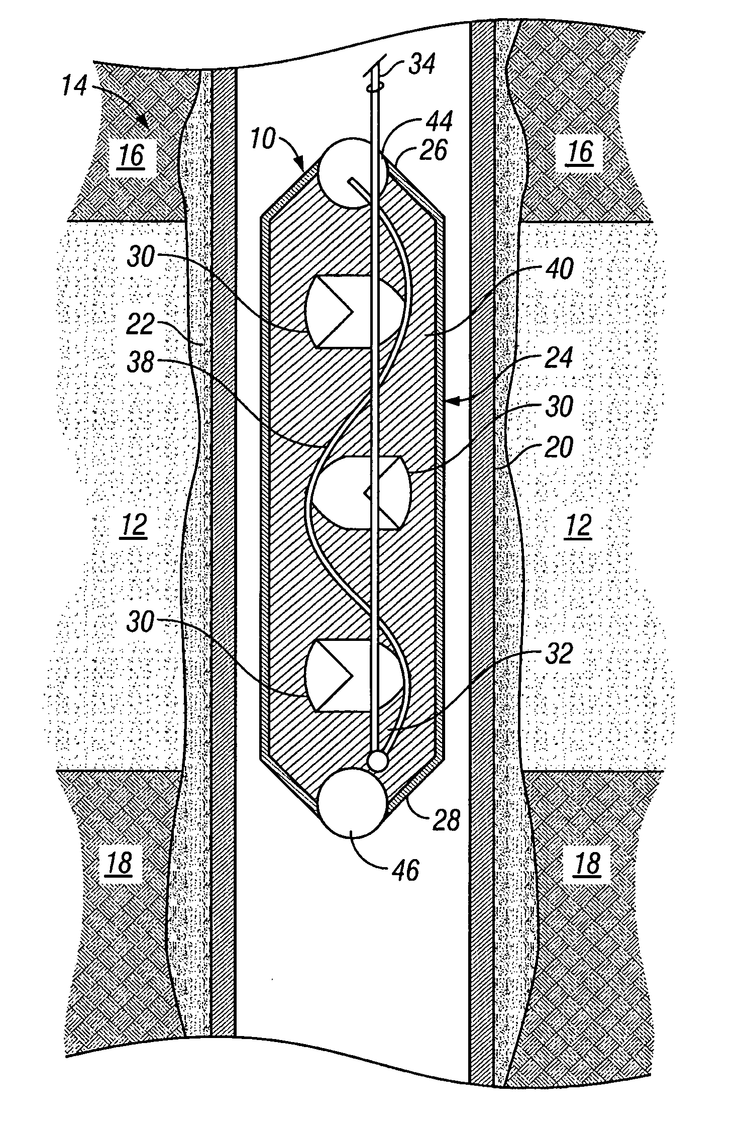
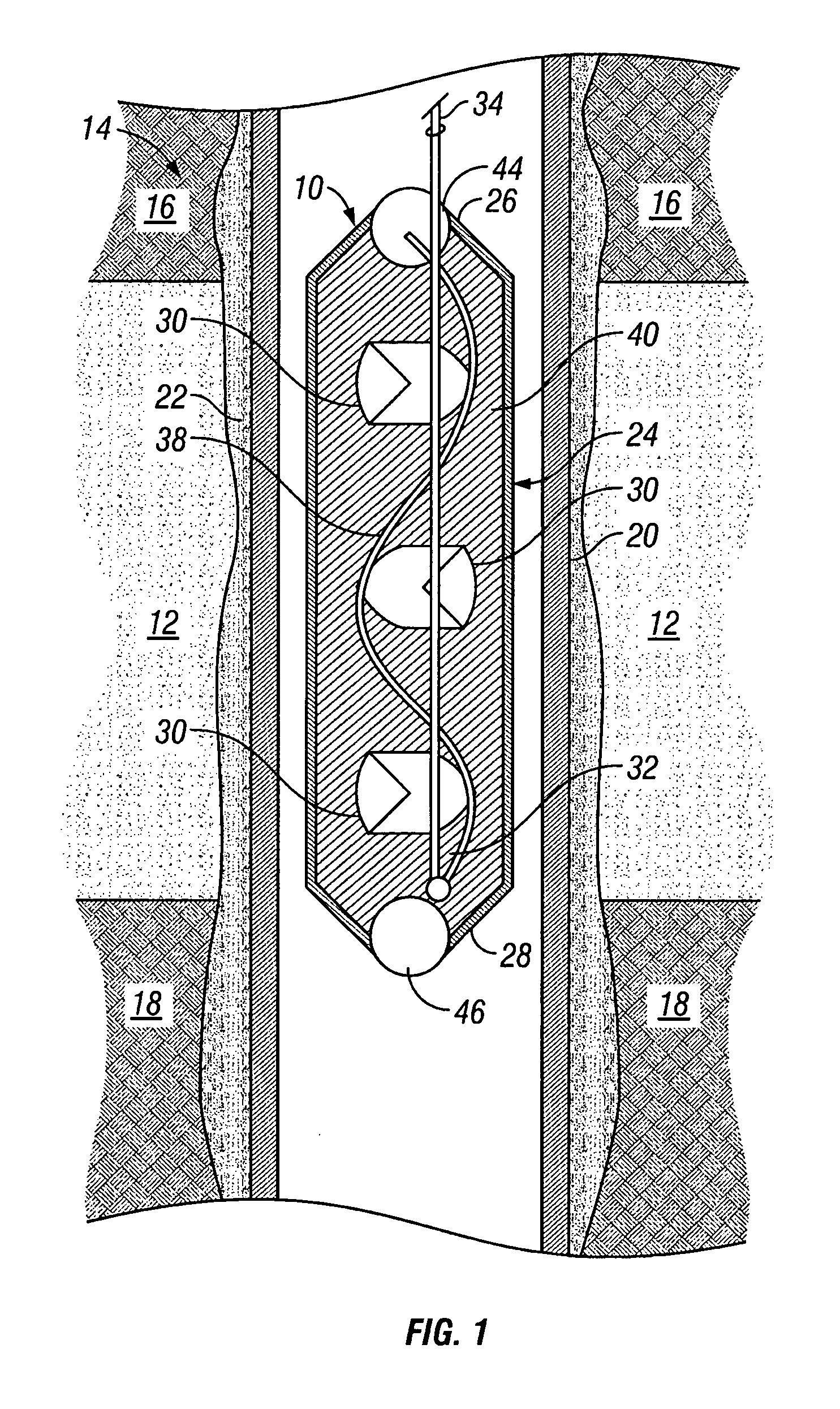
[0021] With reference now to the drawings in general and to FIG. 1 in particularly, there is shown therein an apparatus constructed in accordance with a first preferred embodiment of the present invention and designated generally by the reference numeral 10. The apparatus 10 is adapted to stimulate production from a hydrocarbon-containing formation or strata 12 in an oil or gas well 14.

[0022] An illustrative well environment is shown in FIG. 1 and comprises shale zones 16 and 18 above and below the formation 12. In most instances, the apparatus 10 will be used in a cased interval of the well 14, and the casing of the well 14 is indicated at 20 with the cement in the annulus designated at 22.

[0023] The apparatus 10 comprises a container 24 sized to be received and supported in the well 14 at a level adjacent the formation 12. Preferably, the container 24 is elongated having first and second ends 26 and 28.

[0024] The apparatus 10 further comprises at lea...


PUM


Abstract

A method and apparatus for stimulating producing strata in oil or gas wells. The formation is penetrated using existing shaped charges, and an oxygen-rich material then is introduced into the producing formation. Thus, oxygen is available within the formation to sustain an explosive reaction with the existing formation hydrocarbons acting as fuel. This explosive reaction will cause fracturing of the formation and will counteract plugging that often results from the use of conventional shaped charges. In one embodiment, a container encloses shaped charges surrounded by oxygen-rich material. The shaped charges are ignited first, perforating the well casing and any surrounding cement. Additional explosive charges at each end of the container then are ignited. This forces the oxygen-rich material into the perforation tunnels. Alternately, the oxygen can be a part of the shaped charge and projected into the formation with the shaped charge to accomplish the same results.

Description

[0001] This application claims the benefit of the filing date of provisional application Ser. No. 60 / 502,703, entitled “Reactive Stimulation of Oil and Gas Wells,” filed Sep. 12, 2003, the contents of which are incorporated herein by reference.FIELD OF THE INVENTION [0002] The present invention relates to methods and devices for stimulating producing formations in oil and gas wells to increase production. BACKGROUND OF THE INVENTION [0003] The quantity of oil and gas production from a hydrocarbon bearing strata into a borehole is influenced by many physical factors. Darcey's flow equation, which defines flow in a well, takes into account the reservoir constants of temperature, viscosity, permeability, reservoir pressure, pressure in the borehole, thickness of the producing strata, and the area exposed to flow. [0004] It has long been known that increasing the exposed flow area in a producing well increases production. For example, it is known that drilling a larger diameter hole exp...

Claims


Application Information

Patent Timeline
Patent Type & Authority Applications(United States)
IPC IPC(8): E21B43/24
CPCE21B43/117E21B43/248
Inventor BOND, LESLEY O.HUNT, ERCILL RAYBARNETT, GLENN BOB
Owner BOND LESLEY O
Why Eureka
Try Eureka