
Apparatus and method for managed pressure drilling

a pressure management and pressure technology, applied in the direction of survey, sealing/packing, borehole/well accessories, etc., can solve the problems of affecting the drilling operation, so as to prevent blowouts

Active Publication Date: 2007-05-03
TRANSOCEAN SEDCO FOREX VENTURES LTD +1
View PDF99 Cites 64 Cited by
  • Summary
  • Abstract
  • Description
  • Claims
  • Application Information

AI Technical Summary

Benefits of technology

"The present invention is a drilling system and method that manages pressure in risers during drilling operations. It includes a main marine riser, a concentric riser support body, a telescopic joint, and a riser rotating control device. The system employs a main riser and a concentric riser to control fluid density and prevent abnormal pressures from entering the riser. The invention also includes a method of injecting fluids of different densities and measuring relevant fluid flow parameters to control the blowout preventer. The technical effects of the invention include preventing blowouts, managing pressure in risers, and controlling influxes of abnormal fluids during drilling operations."

Problems solved by technology

Due to limitations in the physical characteristics of existing marine risers present pressure management techniques cannot be implemented without substantial additional cost and / or time.
However, the Hermann et al method and apparatus require the marine riser system to be substantially disassembled before the concentric riser can be deployed.
Disassembling the marine riser system adds significant time and cost to the drilling operation.
This results in the potential for differential movement of the riser away from the well centerline that could cause eccentric side loading of wellbore annular sealing element.
Further, the Hermann et al method employs the upper annular blow-out preventor of the existing BOP to effectively seal and isolate the annulus between the lower end of the concentric riser and the lower end of the marine riser rendering it unavailable for its primary well control function.
The Hannegan method and apparatus has similar limitations with respect to the time and cost of installing and operating the system.
Additionally, without an concentric riser, the burst pressure capacity of the conventional marine riser limits the maximum annular pressure that may be imposed.

Method used


Image

  • Apparatus and method for managed pressure drilling
  • Apparatus and method for managed pressure drilling
  • Apparatus and method for managed pressure drilling

Examples


Embodiment Construction

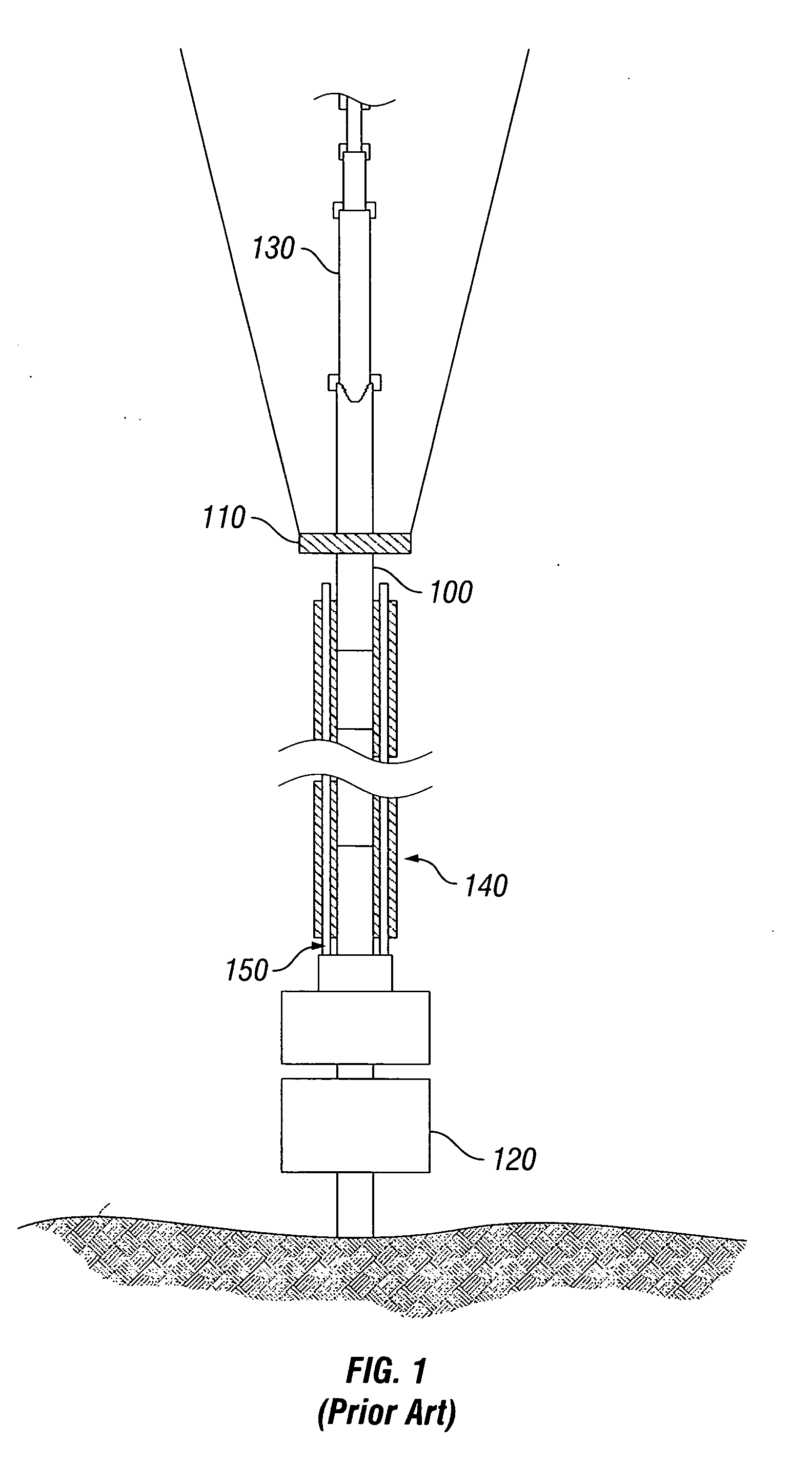
[0031]FIG. 1 shows a conventional riser drilling system. A conventional riser system includes marine riser (100), riser tensioning system (110), blowout preventor (120), telescopic joint (130), auxiliary buoyancy (140) and auxiliary lines (150).

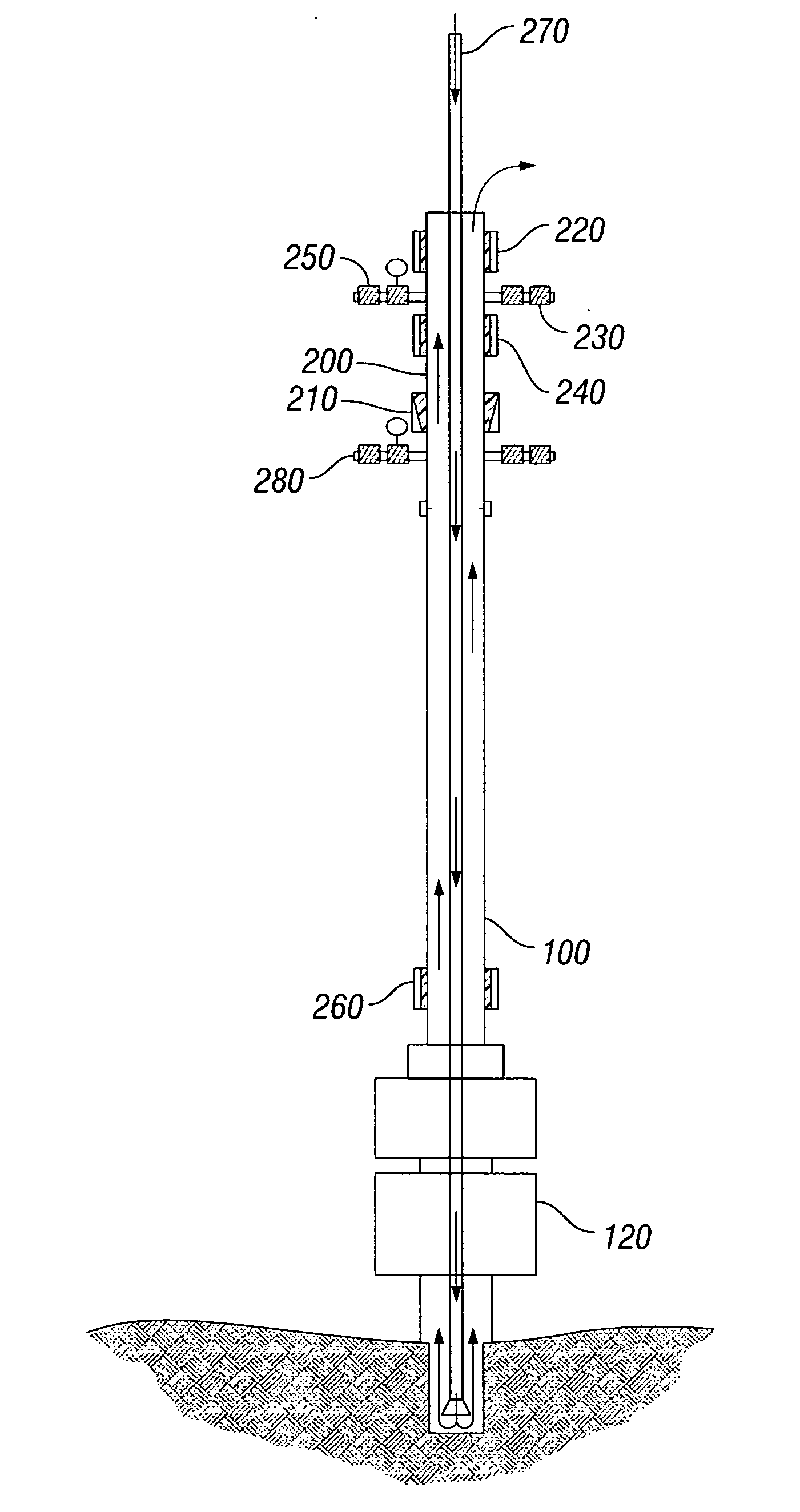
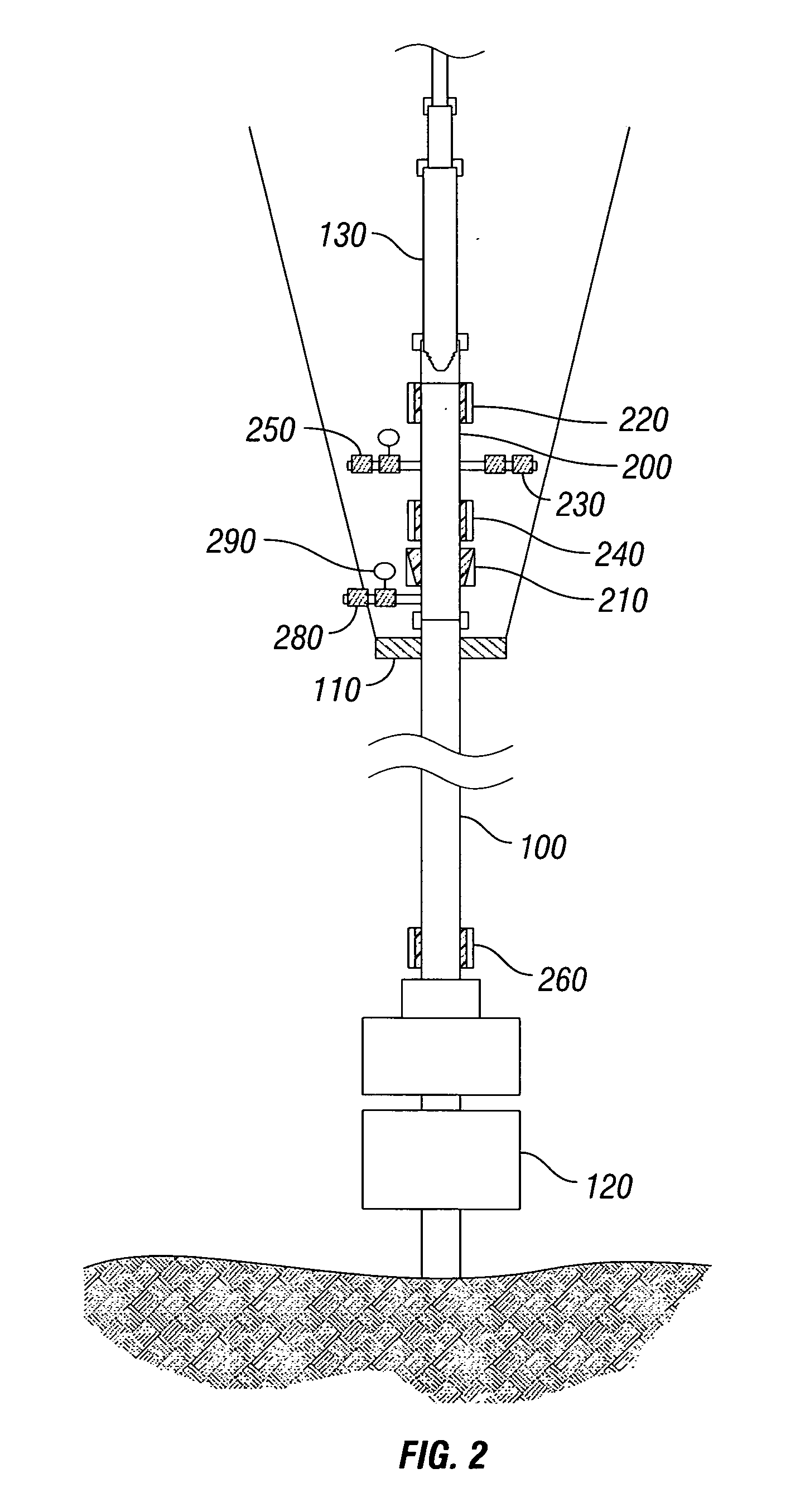
[0032]FIG. 2 shows a preferred embodiment of the invention. Specifically, FIG. 2 shows a marine riser (100) and a riser telescopic joint (130). A riser tensioning system (110) supports and maintains a constant tension on marine riser (100). The bottom of marine riser (100) is connected to a sub-sea blowout preventor (120). Sub-sea blowout preventor (120) is connected to a wellhead (not shown). Positioned above riser tensioning system (110) is the concentric riser support body (200). Concentric riser support body (200) mates with marine riser (100) and telescopic joint (130). Although FIG. 2 does not show any marine riser joints above concentric riser support body (200), one skilled in the art readily understands that such an arrangement is p...


PUM


Abstract

A drilling system employing a main tubular having a plurality of fluid inlet and outlet conduits positioned thereon and a concentric inner tubular having a plurality seals for sealing the annular space between the concentric inner and main tubulars. The fluid inlet and outlet conduits work in cooperation with the annular seals to selectively open and close for effective management of pressure within the tubulars.

Description

CROSS-REFERENCE TO RELATED APPLICATIONS [0001] This application is related to provisional Patent Application No. 60 / 728,542, filed Oct. 20, 2005 entitled “Apparatus and Method for Managed Pressure Drilling.”TECHNICAL FIELD [0002] This invention relates to a novel method and apparatus for offshore drilling operations. In particular, this invention relates to a method and apparatus for employing a concentric, high-pressure marine riser in deep water offshore drilling. In addition, this invention relates to fluid handling in a riser in the event of an unexpected influx of hydrocarbon, fresh water, natural gas, or other pressurized fluid encountered during drilling operations. BACKGROUND OF THE INVENTION [0003] Presently a number of hydrocarbon drilling techniques have been proposed to better manage pressures within or exerted upon a wellbore during drilling activities. Broadly, these techniques encompass two categories of wellbore pressure control. In the first, a “closed loop” circula...

Claims


Application Information

Patent Timeline
Patent Type & Authority Applications(United States)
IPC IPC(8): E21B7/12E21B49/00E21B47/00E21B34/04E21B43/01E21B29/12E21B33/00E21B41/04E21B43/36
CPCE21B17/01E21B21/08E21B33/085E21B21/082
Inventor KOZICZ, JOHNJURAN, TIMLEGAULT, ANDYBLACK, SANDYMACKAY, JOHNNIVEN, SCOTTSNEDDON, IAIN
Owner TRANSOCEAN SEDCO FOREX VENTURES LTD
Learn More