Fuel injector having a separable armature and pintle

a fuel injector and separable technology, applied in the field of fuel injectors, can solve the problems of high cost of piezo-stack and driver, high volume applications, and complex control systems, and achieve the effects of reducing the risk of valve bounce at the injector closing, reducing the risk of valve bounce, and greatly reducing theinertia of the pintl

Active Publication Date: 2007-05-03
BORGWARNER LUXEMBOURG OPERATIONS SARL +1
View PDF6 Cites 14 Cited by
  • Summary
  • Abstract
  • Description
  • Claims
  • Application Information

AI Technical Summary

Benefits of technology

[0012] By decoupling the armature from the pintle, the use of squeeze film damping gaps that are not hard stops is avoided, thus avoiding the need to carefully control such gaps during manufacture. The minimum upper air gap between the armature and an upper stop is always zero because, due to decoupling of the armature from the pintle, the armature always continues to travel to the upper stop after the pintle has reached its closed or retracted position. Because of the separation of the mass of the armature from the pintle, the inertia of the pintle is greatly reduced, the risk of after-injections due to valve bounce at injector closing is alleviated.
[0013] In order to further reduce the risk of valve bounce during opening of the injector, a small amount of fluid shear damping may be introduced by controlling the radial gap between at least a portion of the pintle and / or the armature and a surrounding portion of the injector body and / or solenoid. Alternatively, or additionally, a controlled frictional force may be introduced by means of a friction member, such as a radially biased pin, abutting a side surface of the pintle and / or the armature.

Problems solved by technology

The outwardly opening piezo-electric actuated injector has demonstrated the highest potential for reducing fuel consumption, but the cost of the piezo-stack and driver is prohibitive for high volume applications.
However, piezo-electric fuel injectors are very costly to produce compared to solenoid actuated injectors and require complex and costly control systems for operation of the piezo-stack.
However, known solenoid actuated fuel injectors cannot provide the same level of performance as piezo-electric actuated devices, mainly due to the lower opening force achievable by electromagnetic solenoid actuators and the slower rise of force over time.
A particular problem with known outwardly opening solenoid actuated fuel injectors when operated at high speed is valve bounce.
Due to the elasticity of the valve surfaces and the pintle stem, the pintle head tends to rebound from the valve seat, causing the injector to re-open.
Such valve bounce can cause one or more unmetered after injections of fuel delivery after injector closing.
This problem is particularly acute in high pressure applications.
Manufacturing and adjusting such air gaps has proven to be very expensive and difficult to control, with additional problems of durability and performance, particularly in relation to differential thermal expansion of different parts of the injector during use.

Method used


Image

  • Fuel injector having a separable armature and pintle
  • Fuel injector having a separable armature and pintle
  • Fuel injector having a separable armature and pintle

Examples


first embodiment

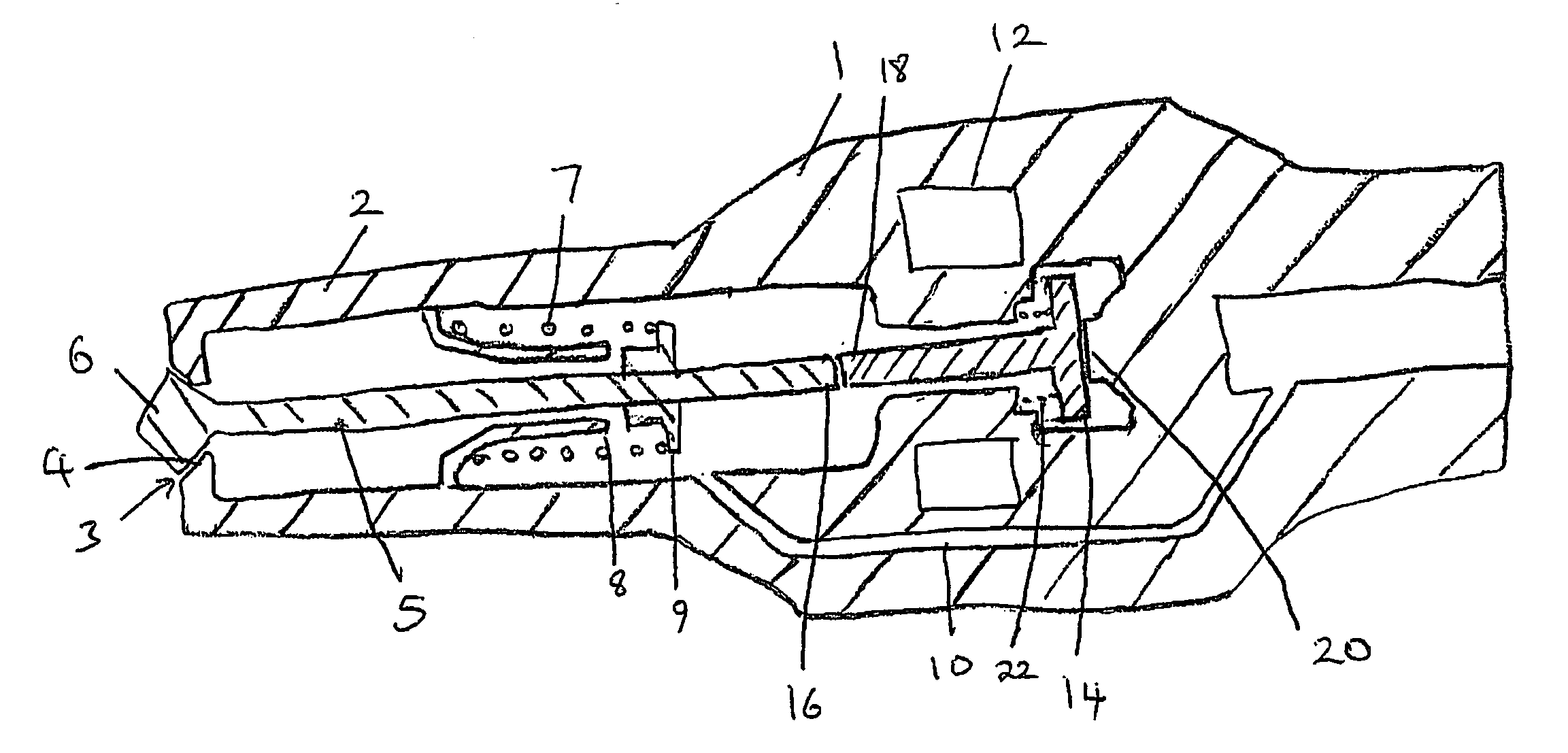
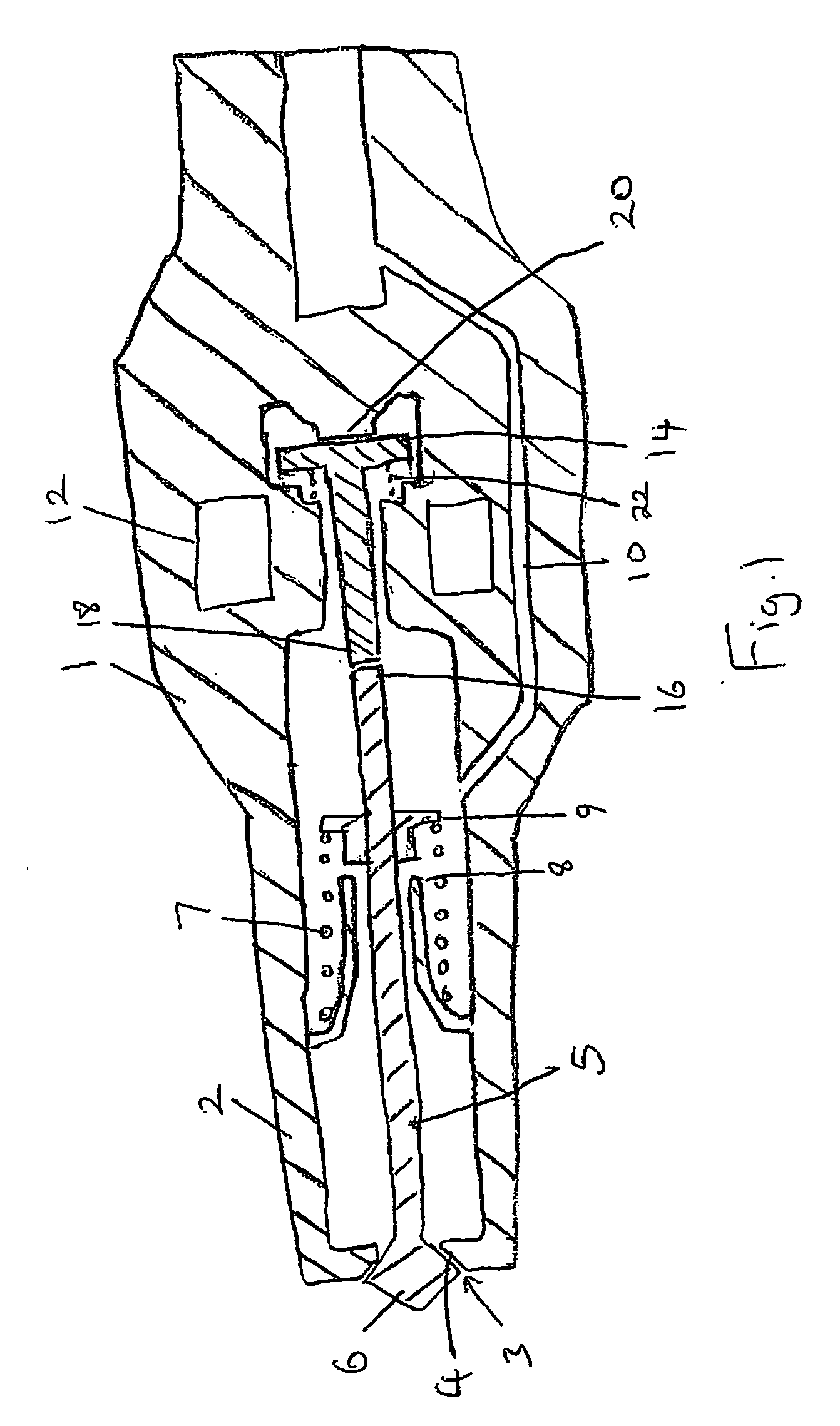
[0020] A fuel injector according to the present invention is shown in FIG. 1. The fuel injector comprises an injector body 1 having a tip portion 2 having a spray aperture 3 at a distal end thereof. An outwardly opening valve pintle 5 extends within the tip portion 2, the pintle 5 having a head portion 6 engageable with a valve seat 4 surrounding the spray aperture 3 to close the spray aperture 3.

[0021] The pintle 5 is axially moveable within the injector body 1 between a retracted position wherein the head portion 6 engages the valve seat 4 and an extended position wherein the head portion 6 is spaced from the valve seat 4. A return spring 7 is mounted within the tip portion, biasing the pintle 5 towards its retracted position. An end stop 8 mounted on the injector housing 1 cooperates with a collar 9 on the pintle to limit the extension of the pintle 5 and define the extended position of the pintle 5.

[0022] The interior of the tip portion 2 of the injector body 1 communicates wit...

second embodiment

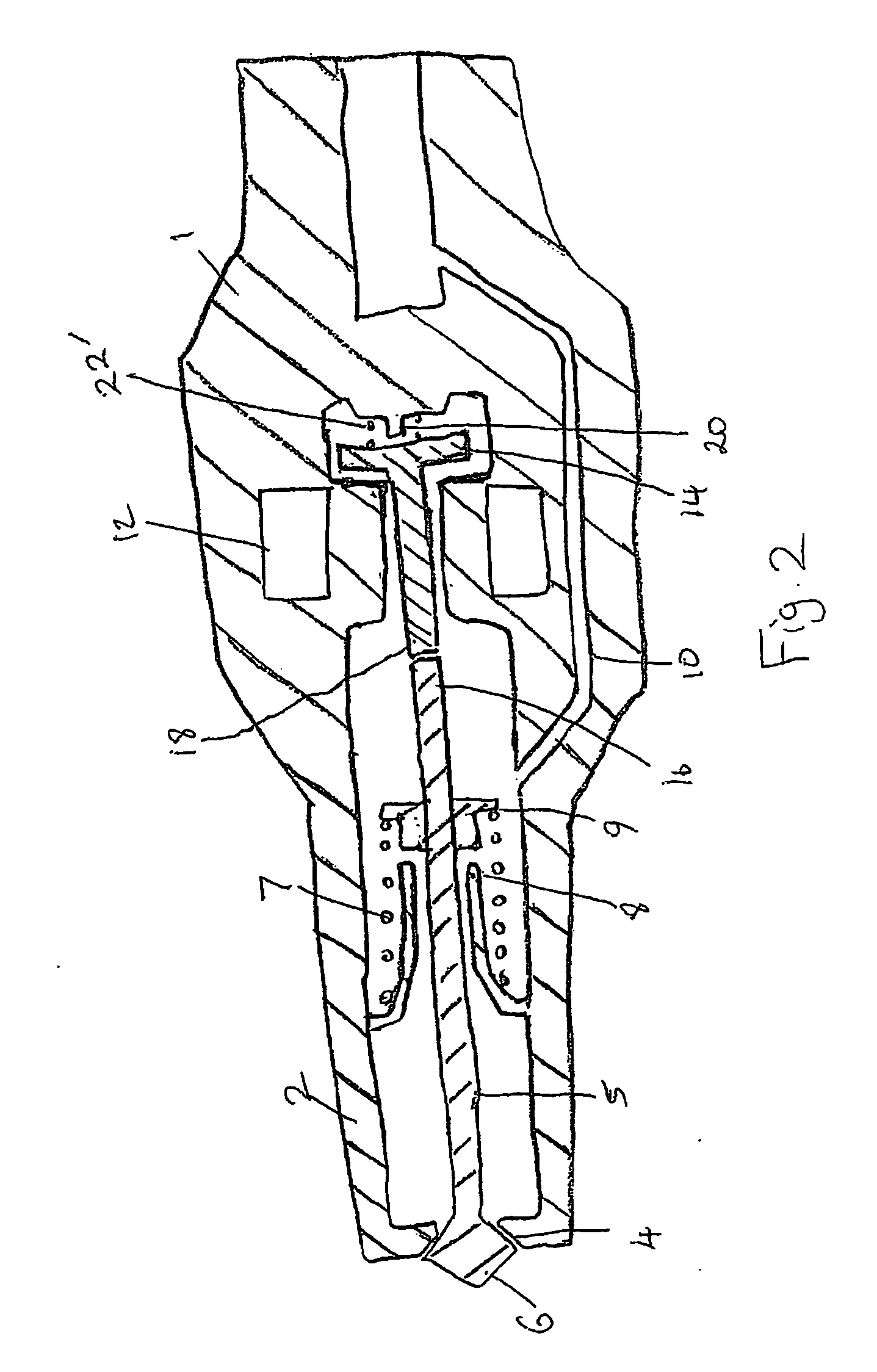
[0030] In a second embodiment, shown in FIG. 2, the armature return spring 22′ is provided between the armature 14 and the upper stop 20 to bias the armature 14 into contact with the pintle 5. In such embodiment, the armature return spring 22′ can be selected to calibrate the injector, such spring acting against the main return spring 7 to provide a force acting on the pintle 5 in a valve opening direction.

[0031] In an alternative embodiment (not shown) the armature may be upwardly biased away from the pintle, as in the embodiment shown in FIG. 1. However, instead of locating the armature return spring between the housing and the armature—as shown in FIG. 1—the armature return spring may act between the pintle 5 and the lower portion 18 of the armature 14, such that the return spring is referenced to the pintle 5 rather than the housing 1. By locating the armature return spring adjacent the pintle 5, an upward bias is provided that does not reduce the available armature magnetic for...


PUM


Abstract

A fuel injector comprises an injector body having a tip portion defining a spray aperture; a pintle extending within the tip portion for axial movement between an extended position and a retracted position, the pintle having a head portion engageable with the spray aperture to close the spray aperture when the pintle is in its retracted position; biasing means being provided for biasing the pintle towards its retracted position; and solenoid means for selectively moving the pintle into said extended position; said solenoid means comprising an electromagnetic coil and a moveable armature capable of being acted upon by the coil to urge the pintle towards its extended position; wherein the pintle and armature are separable from one another whereby the armature can decouple from the pintle when the pintle moves from its extended position to its retracted position.

Description

TECHNICAL FIELD OF INVENTION [0001] The present invention relates to a fuel injector and in particular to a fuel injector for direct injection of gasoline into the combustion chamber of an internal combustion engine. BACKGROUND OF INVENTION [0002] Modern direct injection gasoline engines require fuel injectors to operate under extreme conditions of temperature and pressure and with high fuel pressures. Furthermore, the fuel injector must open and close very rapidly in order to provide multi-pulse injection cycles required for fuel efficiency and low emissions. [0003] Current high pressure direct injection fuel injectors either use inwardly opening valves (nozzle type or multi-hole director) in conjunction with solenoid actuation or outwardly opening valves using piezo-electric actuation. The outwardly opening piezo-electric actuated injector has demonstrated the highest potential for reducing fuel consumption, but the cost of the piezo-stack and driver is prohibitive for high volume...

Claims


Application Information

Patent Timeline
Patent Type & Authority Applications(United States)
IPC IPC(8): F02M51/00
CPCF02M51/066F02M61/08
Inventor HOFFMANN, GUYCLERX, FRANK A.
Owner BORGWARNER LUXEMBOURG OPERATIONS SARL
Why Eureka
Try Eureka