DC-DC converter and control circuit thereof

a technology of dc-dc converter and control circuit, which is applied in the direction of dc-dc converter, power conversion system, instruments, etc., can solve the problems of easy instability of output dc voltage, and achieve the effect of facilitating the design of stabilizing the feedback system and stable operation

Inactive Publication Date: 2007-05-03
COLLABO INNOVATIONS INC
View PDF6 Cites 20 Cited by
  • Summary
  • Abstract
  • Description
  • Claims
  • Application Information

AI Technical Summary

Benefits of technology

[0027] In the DC-DC converter and its control circuit according to the present invention, the DC-DC converter, in which the relationship between the duty ratio and the output DC voltage is nonlinear, can linearize the relationship between the output DC voltage and the error signal that is obtained by amplifying the error between the output DC voltage and a target ...

Problems solved by technology

This indicates that, as the output DC voltage Vo is higher than the input DC voltage Vi, the output DC voltage Vo fluctuates s...

Method used


Image

  • DC-DC converter and control circuit thereof
  • DC-DC converter and control circuit thereof
  • DC-DC converter and control circuit thereof

Examples


first embodiment

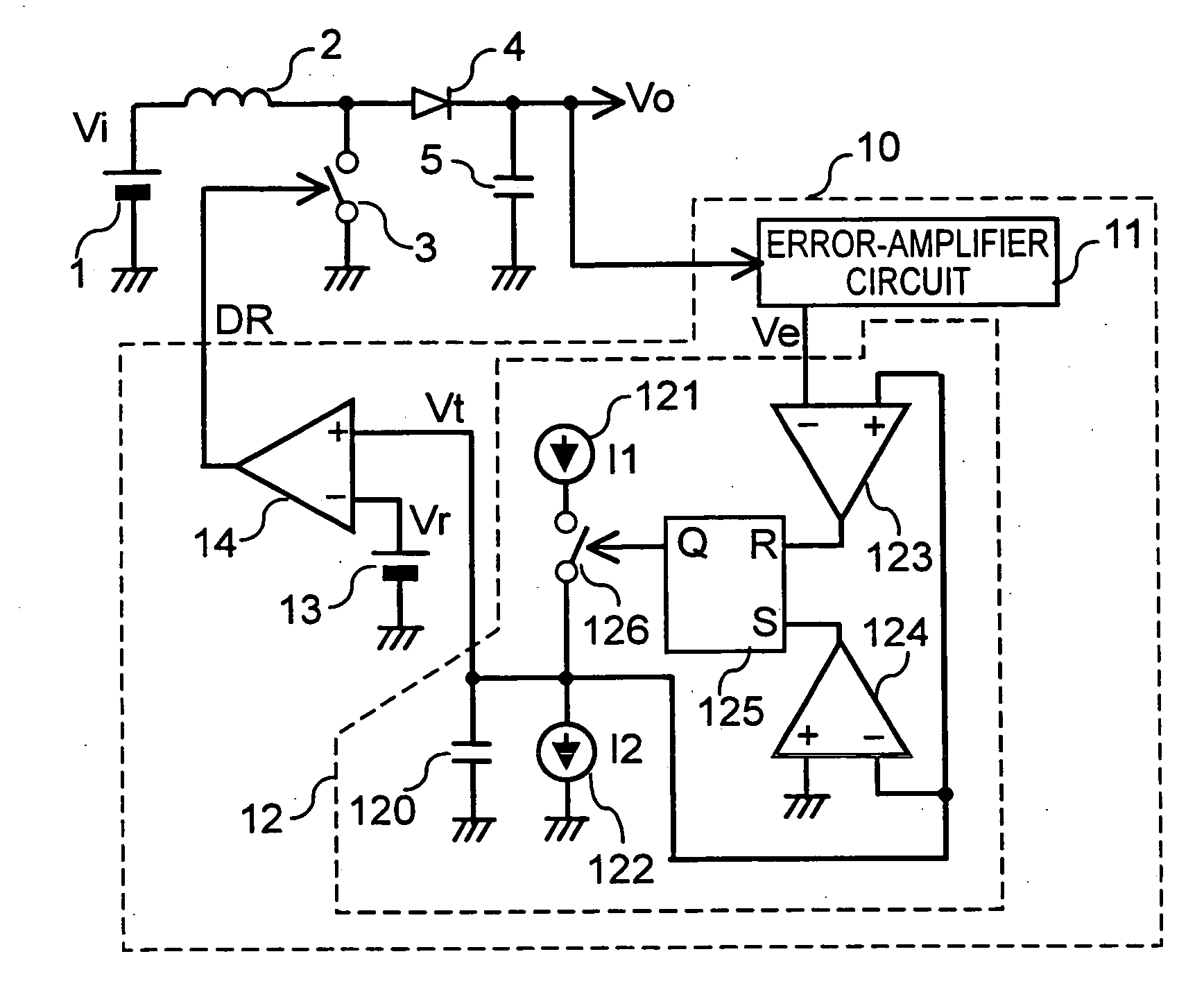
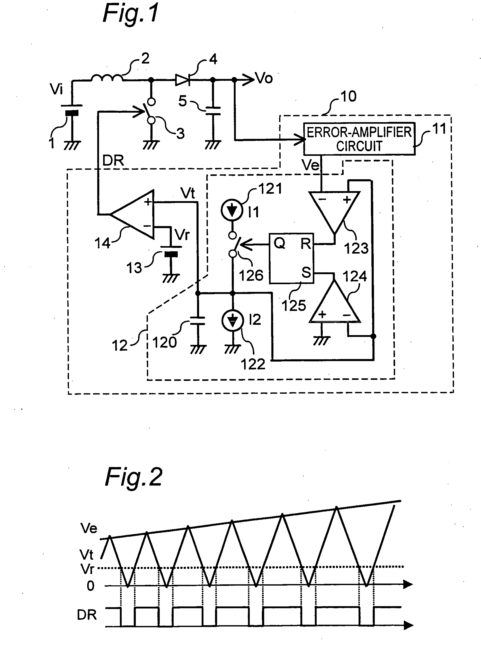
[0042]FIG. 1 is a circuit diagram showing the configuration of a DC-DC converter and its control circuit according to the present invention.

[0043] As shown in FIG. 1, an input DC power supply 1, such as a battery, is connected to one terminal of an inductor 2. To the other terminal of the inductor 2, one terminal of a switching device 3 formed of a MOSFET and one terminal of a rectifying means 4 formed of a diode are connected. The other terminal of the switching device 3 is grounded. One terminal of a smoothing means 5 formed of a capacitor is grounded, and the other terminal thereof is connected to the other terminal of the rectifying means 4. Furthermore, the other terminal of the rectifying means 4 serves as an output terminal and is connected to a control circuit 10. The inductor 2 and the switching device 3 are connected in series, and this series circuit is connected in parallel with the input DC power supply 1. The rectifying means 4 is connected to the connection point of t...

embodiment 1

[0050] In the steady state of the control circuit of the DC-DC converter according to Embodiment 1 of the present invention, wherein the output DC voltage Vo is stabilized, the relationships represented by Expressions (4) and (5) described below are established.

Vo=Vi / (1−D)=Vi·Ve / Vr  (4)

∂Vo / ∂Ve=Vi / Vr  (5)

[0051] As described above, the relationship between the error signal Ve and the output DC voltage Vo is linear, and the rate of change (∂Vo / ∂Ve) of the output DC voltage Vo due to the error signal Ve does not depend on the level of the error signal Ve. For this reason, the design of stabilizing the feedback system is facilitated.

[0052] Furthermore, because the duty ratio D is determined by the error signal Ve and the reference signal Vr as indicated in Expression (3), the maximum duty ratio Dmax can be set using the maximum value of the error signal Ve and the reference signal Vr.

[0053]>

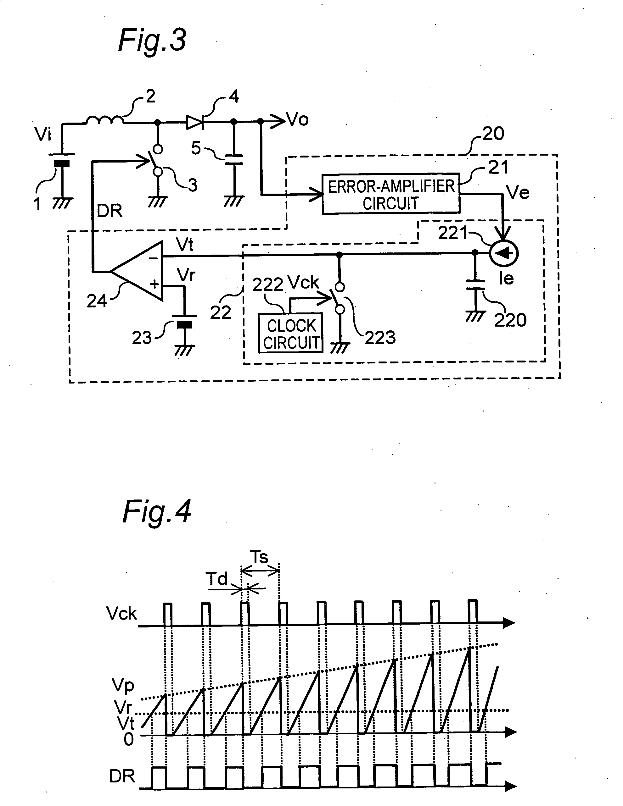
[0054]FIG. 3 is a circuit diagram showing the configuration of a DC-DC converter and its contr...

embodiment 2

[0062] In the steady state of the control circuit of the DC-DC converter according to Embodiment 2 according to the present invention, wherein the output DC voltage Vo is stabilized, the relationships represented by Expressions (9) and (10) described below are established. Vo=Vi / (1-D)(9) ⁢=Vi·Ve·Ts / (Vr·C⁢ ⁢2·Re) ∂Vo / ∂Ve=Vi·Ts / (Vr·C⁢ ⁢2·Re)(10)


PUM


Abstract

The present invention is intended to provide a DC-DC converter, in which the relationship between the duty ratio of a drive signal and the output DC voltage is nonlinear, being characterized in that the relationship between an error signal and the output DC voltage is linear, and that the design of stabilizing the feedback system is facilitated. The DC-DC converter comprises an error-amplifier circuit for generating the error signal that is obtained by amplifying the error between the output and a target value, an oscillating circuit for generating a triangular wave signal having an amplitude corresponding to the error signal, and a comparison circuit for comparing the triangular wave signal with a reference signal having a predetermined value and for generating the drive signal to turn ON/OFF a switching device.

Description

BACKGROUND OF THE INVENTION [0001] The present invention relates to a DC-DC converter for converting a DC input voltage into a target output voltage by repeatedly storing energy in an inductor and releasing the energy from the inductor through the ON / OFF operation of a switching device, and to a control circuit thereof. [0002] In a power supply circuit in which an input DC voltage is input from an input DC power supply, and output DC voltages serving as power supply voltages for various electronic circuits are output, for example, when an output DC voltage higher than the input DC voltage is output, a step-up converter is used. [0003] As a general step-up converter and its control circuit, a converter and its control circuit configured as shown in FIG. 9 are known. A first conventional step-up converter and its control circuit will be described below referring to FIG. 9. In FIG. 9, numeral 1 designates an input DC power supply, such as a battery, numeral 2 designates an inductor, nu...

Claims


Application Information

Patent Timeline
IPC IPC(8): G05F1/00
CPCH02M3/1563
Inventor ISHII, TAKUYAAKASHI, HIROKIISHIMARU, MAKOTOKONISHI, YOSHIYUKI
Owner COLLABO INNOVATIONS INC
Why Eureka
Try Eureka