Current sensor and method of manufacturing the same

a current sensor and sensor technology, applied in pulse generators, pulse techniques, instruments, etc., can solve the problems of inability to accurately detect current, and limited gap separation distance to the thickness of hall ic, so as to reduce separation distance, accurate positioning, and increase sensitivity

Inactive Publication Date: 2007-05-03
DENSO CORP
View PDF13 Cites 9 Cited by
  • Summary
  • Abstract
  • Description
  • Claims
  • Application Information

AI Technical Summary

Benefits of technology

[0014] The magnetic core and the Hall element are formed to the substrate by semiconductor manufacturing techniques. Therefore, the Hall element can be placed in the gap to be accurately positi

Problems solved by technology

As a result, the current sensor may not accurately detect the current.
As a result, the current sensor may not accurately detect the curren

Method used


Image

  • Current sensor and method of manufacturing the same
  • Current sensor and method of manufacturing the same
  • Current sensor and method of manufacturing the same

Examples


first embodiment

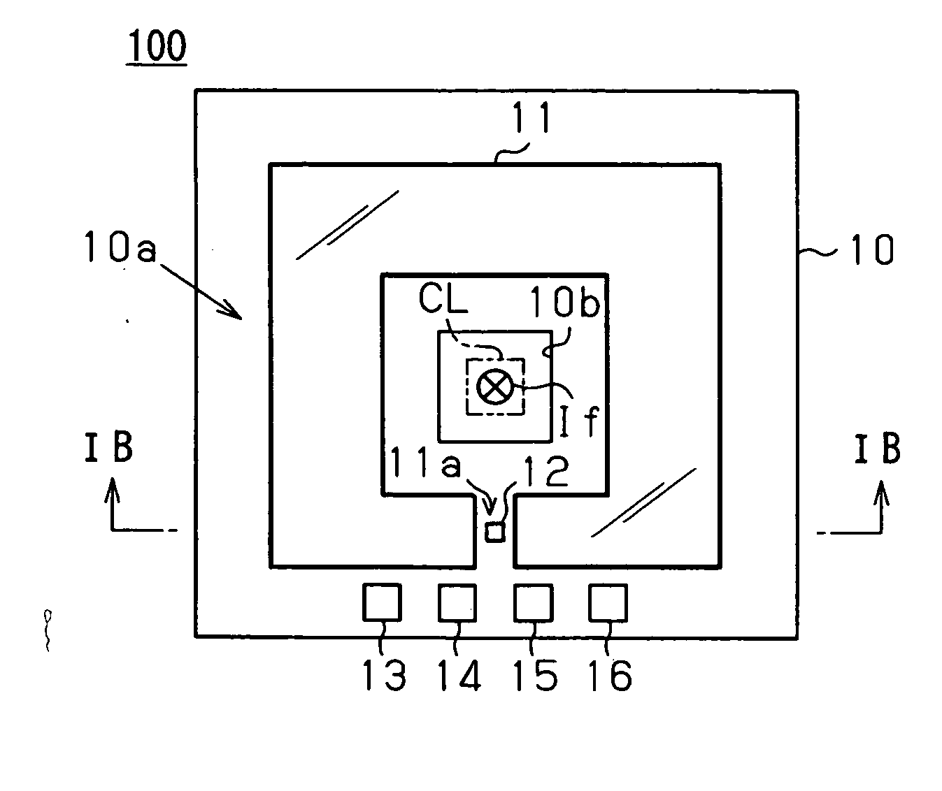
[0023] Referring to FIGS. 1A and 1B, a current sensor 100 includes a semiconductor substrate 10 with a surface 10a and a center hole 10b, a ring-shaped magnetic core 11 with a gap 11a, a vertical Hall element 12.

[0024] The center hole 10b penetrates through the substrate 10 in a thickness direction of the substrate 10. A conductor CL through which a current If to be detected flows is inserted through the center hole 10b. The magnetic core 11 is made of a magnetic material such as permalloy and formed to the surface 10a to surround the center hole 10b. The Hall element 12 is placed in the gap 11a such that a control current Ib shown in FIG. 2B flows in a direction perpendicular to the surface 10a. The Hall element 12 has terminals electrically connected to wire bonding pads 13-16 formed on the surface 10a.

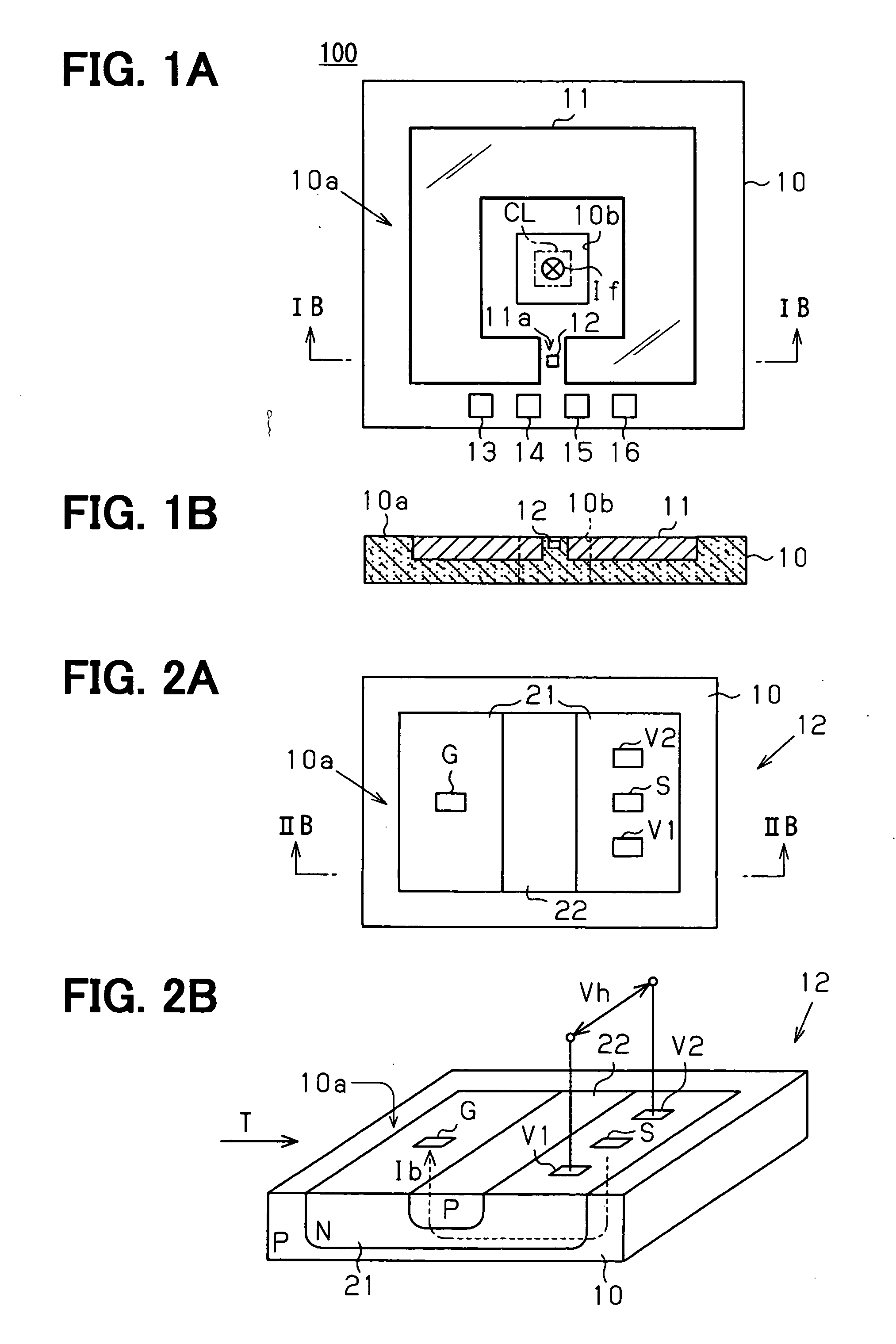
[0025]FIGS. 2A and 2B illustrate the Hall element 12 in detail.

[0026] As shown in FIG. 2B, when the control current Ib having a perpendicular component to the surface 10a is supp...

second embodiment

[0043] Referring to FIGS. 8A-9D, a current sensor 200 includes a semiconductor substrate 30 with a surface 30a, the magnetic core 11, and the Hall element 12.

[0044] First and second connection terminals 31, 32 are formed on the surface 30a of the substrate 30. As shown in FIG. 8A, the first and second connection terminals 31, 32 are positioned inside and outside the magnetic core 11, respectively. Specifically, the first and second connection terminals 31, 32 are positioned on the opposite side of the magnetic core 11.

[0045] As shown in FIG. 8B, a conductive member 33 for electrically connecting the first and second connection terminals 31, 32 is formed in the substrate 30 to pass under the magnetic core 11. The conductive member 33 has first and second end portions 33a, 33c (see, FIG. 9D) extending perpendicular to the surface 30a and a middle portion 33b (see, FIG. 9D) extending parallel to the surface 30a. The first and second end portions 33a, 33c are connected to the first an...


PUM


Abstract

A current sensor includes a semiconductor substrate, a ring shaped magnetic core having a center opening and a gap and provided to a surface of the substrate, and a Hall element provided to the surface and placed in the gap of the magnetic core such that a control current for operating the Hall element flows perpendicular to the surface of the substrate. The magnetic core and the Hall element are formed to the substrate by semiconductor manufacturing techniques. Therefore, the Hall element can be placed in the gap to be accurately positioned with respect to the magnetic core and the gap can have a reduced separation distance. Thus, the current sensor can have an increased sensitivity and accurately measure a current to be detected.

Description

CROSS REFERENCE TO RELATED APPLICATION [0001] This application is based on and incorporates herein by reference Japanese Patent Application No. 2005-317459 filed on Oct. 31, 2005. FIELD OF THE INVENTION [0002] The present invention relates to a current sensor and a method of manufacturing the current sensor. BACKGROUND OF THE INVENTION [0003] A current sensor has been proposed that detects a current based on characteristics of a Hall element, which is a semiconductor element. When a control current flows through the Hall element and a magnetic field is applied to the Hall element in a direction perpendicular to the control current flow direction, a Hall effect occurs and a Hall voltage is induced across the Hall element. [0004] When a current to be detected flows through a conductor, the magnetic field is generated around the conductor in a direction perpendicular to the detected current flow direction. The magnetic field changes proportional to the amount of the detected current. T...

Claims


Application Information

Patent Timeline
IPC IPC(8): G01R15/20
CPCG01R15/202
Inventor ISHIHARA, MASATO
Owner DENSO CORP
Why Eureka
Try Eureka