Electrochromic glass control device

a control device and glass technology, applied in the field of smart glass, can solve the problems of excessive heat in the resistor and “chatter” in the smart glass material, and achieve the effect of reducing any such potential heat and “chatter” problems

Inactive Publication Date: 2007-05-03
LEVITON MFG
View PDF1 Cites 55 Cited by
  • Summary
  • Abstract
  • Description
  • Claims
  • Application Information

AI Technical Summary

Benefits of technology

[0013] To address the above-discussed deficiencies of light control systems for smart-glass, the present invention teaches a light control system having a full range of dimming for smart-glass. In particular, the present invention provides a light control system having an electrochromic glass control device that acts as an interface between an off-the-shelf dimmer and a electrochromic glass device where the interface converts an asymmetric alternating current (AC) power signal from the dimmer device into a symmetric, amplitude controlled AC output signal for controlling the tint of the electrochromic or smart-glass device. A symmetric AC output signal may be defined as a signal having symmetry about its peaks and / or symmetry about its zero-crossing points. An asymmetric AC power signal fails to exhibit symmetry either about its peaks or its zero-crossing point. The electrochromic glass control device employs a controllable semiconductor load across the output of the dimmer. The controllable semiconductor load has various advantages over a fixed resistor placed in parallel to the output of the dimmer. For example, a fixed resistor may cause various problems including excessive heat in the resistor and “chatter” in the smart-glass material, wherein chatter is caused by the sudden asymmetric switching of the output signal from the dimmer. The present invention helps reduce any such potential heat and “chatter” problems.

Problems solved by technology

For example, a fixed resistor may cause various problems including excessive heat in the resistor and “chatter” in the smart-glass material, wherein chatter is caused by the sudden asymmetric switching of the output signal from the dimmer.

Method used


Image

  • Electrochromic glass control device
  • Electrochromic glass control device
  • Electrochromic glass control device

Examples


Embodiment Construction

[0021] The present invention will now be described more fully hereinafter with reference to the accompanying drawings, in which embodiments of the invention are shown. This invention may, however, be embodied in many different forms and should not be construed as limited to the embodiments set forth herein. Rather, these embodiments are provided so that this disclosure will be thorough and complete, and will fully convey the scope of the invention to those skilled in the art.

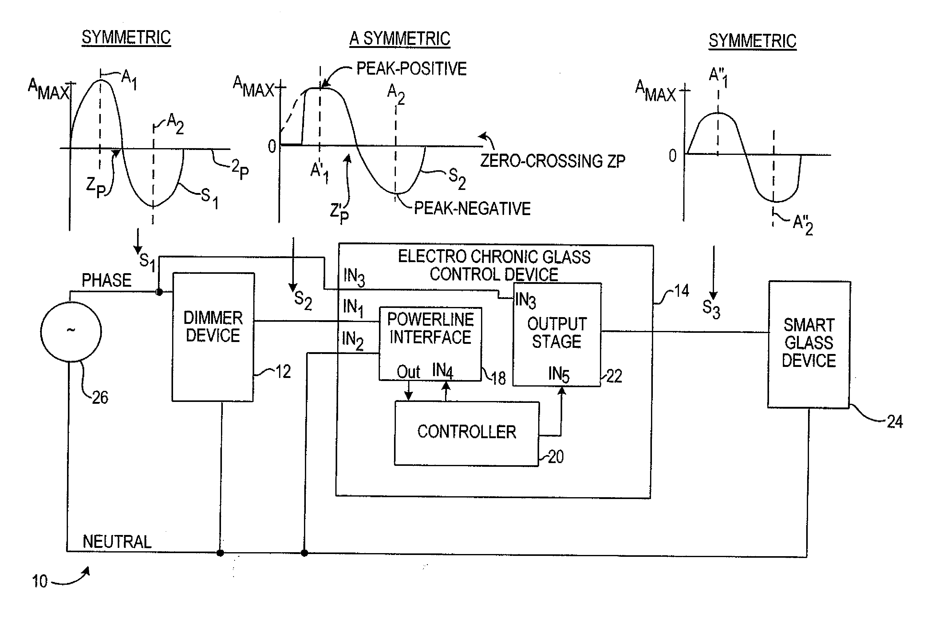
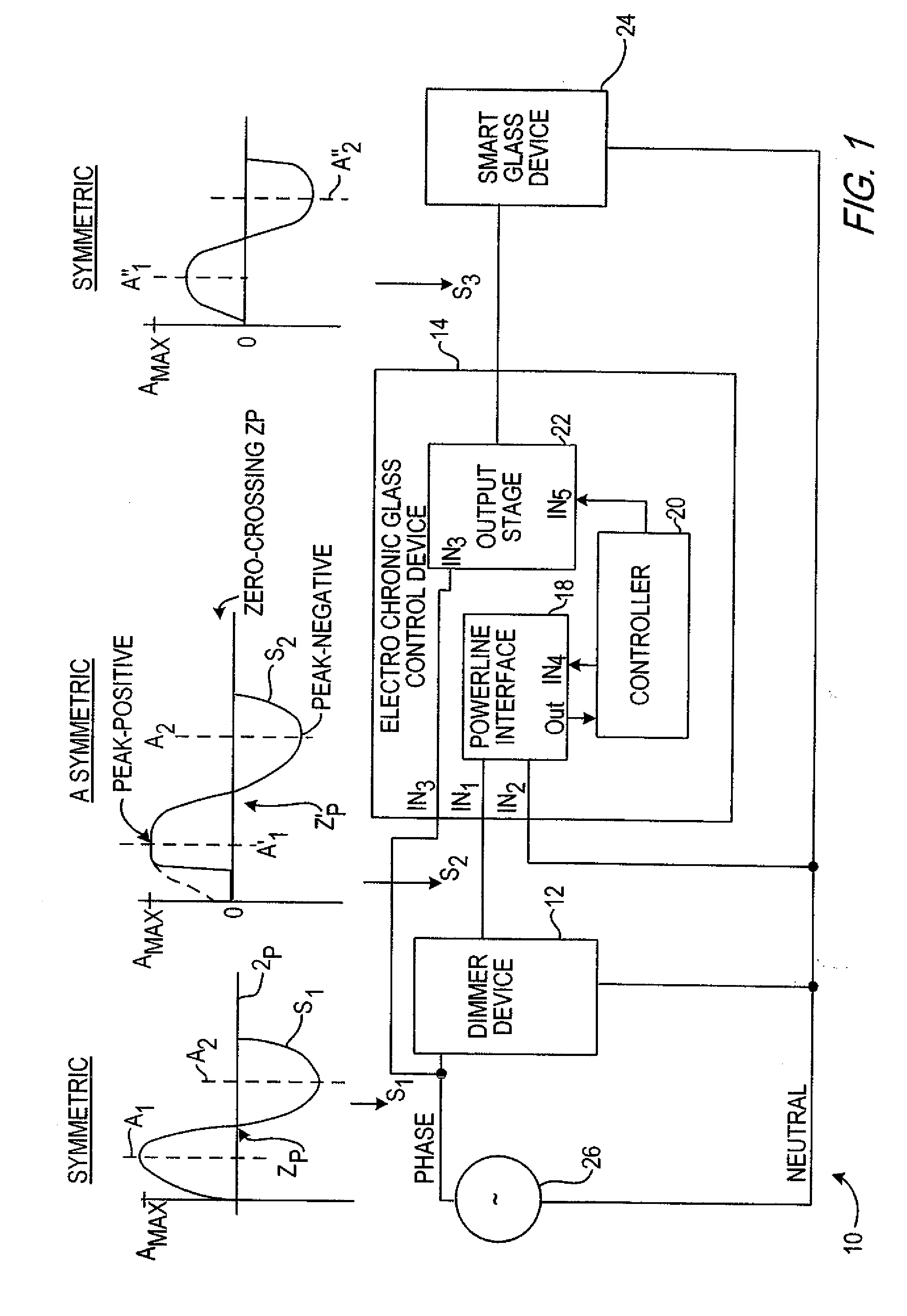
[0022]FIG. 1 represents a block diagram of an electrochromic or smart-glass control system 10 for controlling the tint of a smart-glass device 24 in accordance with an embodiment of the invention. A dimmer device 12 receives a symmetric signal S1 from an alternating current (AC) power source 26 which has phase and neutral lines. Dimmer device 12 generates an asymmetric signal S2 from the symmetric signal S1 relative to the setting of a brightness adjustment control (e.g., slider switch, not shown) which sits on...


PUM

PropertyMeasurementUnit
alternating currentaaaaaaaaaa
electrochromicaaaaaaaaaa
alternating current (ACaaaaaaaaaa

Abstract

A light control system having a full range of dimming for smart-glass by providing an interface between an off-the-shelf dimmer and a electrochromic glass device is disclosed herein. The light control system or electrochromic glass control device acts as an interface that converts an asymmetric alternating current (AC) power signal from the dimmer device into a symmetric, amplitude controlled AC output signal for controlling the tint of the smart-glass device. The electrochromic glass control device includes a powerline interface circuit that receives the asymmetric AC power signal from the dimmer. A controller connects to the powerline interface circuit to generate a control signal responsive to the asymmetric AC power signal. Connecting between the dimmer and the controller, an output stage generates the symmetrical AC output signal responsive to the control signal to control the electrochromic glass device.

Description

FIELD OF THE INVENTION [0001] The present invention relates to ‘smart’ glass, and, more particularly, to an electrochromic glass control device. BACKGROUND OF THE INVENTION [0002] The twenty-first century has been marked by growing integration of technology within commercial buildings and residential homes. Smart homes of this new millennium have independent networks controlling various systems including communications, entertainment, lighting, heating, and security. More homes today are built with expansive great rooms, combination media rooms, cathedral ceilings, large architectural windows and other features that affect the distribution of both natural and electric light. Of particular interest to many architects, developers and builders is chromogenics. Chromogenics is the process by which ‘smart’ windows automatically change from light to dark in response to an environmental condition or in response to an applied voltage, altering the amount of light permitted into a room. [000...

Claims


Application Information

Patent Timeline
Patent Type & Authority Applications(United States)
IPC IPC(8): G02F1/153
CPCG02F1/163
Inventor LIBRETTO, JOHNOSTROVSKY, MICHAELFRID, EUGENEUFTRING, EDWARD
Owner LEVITON MFG
Why Eureka
Try Eureka