Distributed generation system and power system stabilizing method

a technology of distribution generation system and power system, applied in the direction of electric generator control, dynamo-electric converter control, machines/engines, etc., can solve the problems of increasing loss, and affecting the stability of power distribution system

Inactive Publication Date: 2007-05-03
HITACHI LTD
View PDF64 Cites 54 Cited by
  • Summary
  • Abstract
  • Description
  • Claims
  • Application Information

AI Technical Summary

Benefits of technology

[0010] An object of this invention is to suppress the voltage fluctuation in the power system resulting from the provision of the distributed generation by means of an apparatus or facility of a small power capacity.
[0012] Still another object of this invention is to provide a distributed generation which hardly causes disturbance in the power system.

Problems solved by technology

Also, in a wind farm or an offshore wind farm, which has appeared recently and been built with a multitude of wind turbines concentrated in a single site, there may be an adverse possibility that the voltage of the power distribution system fluctuates considerably due to the power output of the wind farm fluctuating to a great extent.
This intrinsically unnecessary compensation of the voltage fluctuation due to the load fluctuation gives rise to the generation of large reactive power, which in turn results in an increase in loss and a decrease in the power generation efficiency in the distributed generation system.
Consequently, when a plurality of distributed generation serves to control the voltage on the distributed feeder so as to maintain it as a predetermined value, control interference may occur among those distributed generation.

Method used


Image

  • Distributed generation system and power system stabilizing method
  • Distributed generation system and power system stabilizing method
  • Distributed generation system and power system stabilizing method

Examples


embodiment 1

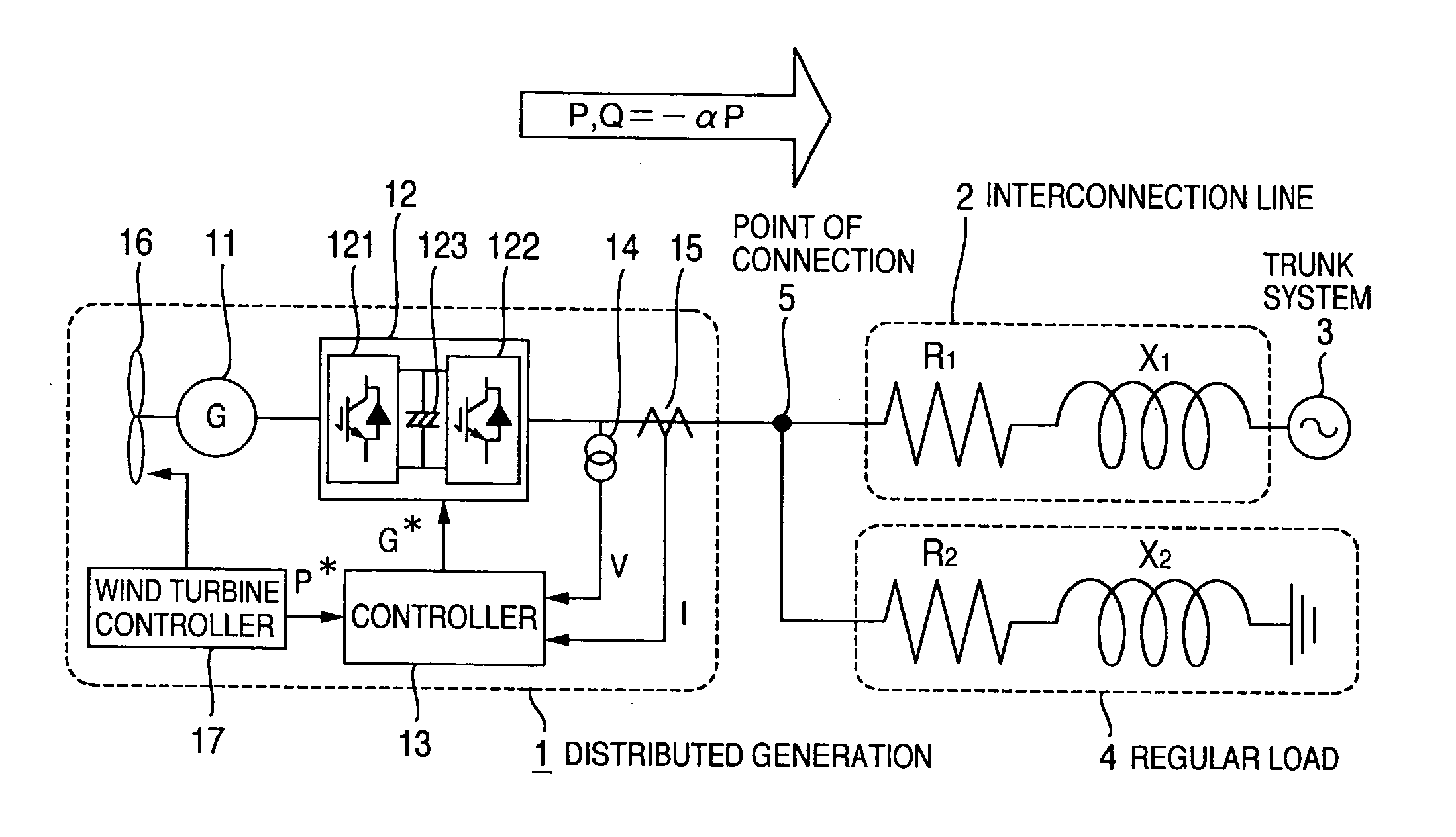
[0033]FIG. 1 schematically shows a block diagram of a distributed generation system provided with a power system stabilizer, as a first embodiment of this invention. A distributed generation 1 is connected via a system interconnection line or cable 2 with a trunk system 3. Let the resistance and the reactance of the impedance of the distribution feeder 2 be represented by R1 and X1, respectively. At the point 5 of interconnection between the distributed generation 1 and the interconnection line 2, or at any point on the interconnection line is connected a regular load 4 such as any of domestic electric appliances or factory machinery which consumes electric power. Similarly, the regular load consists of its resistance R2 and reactance X2.

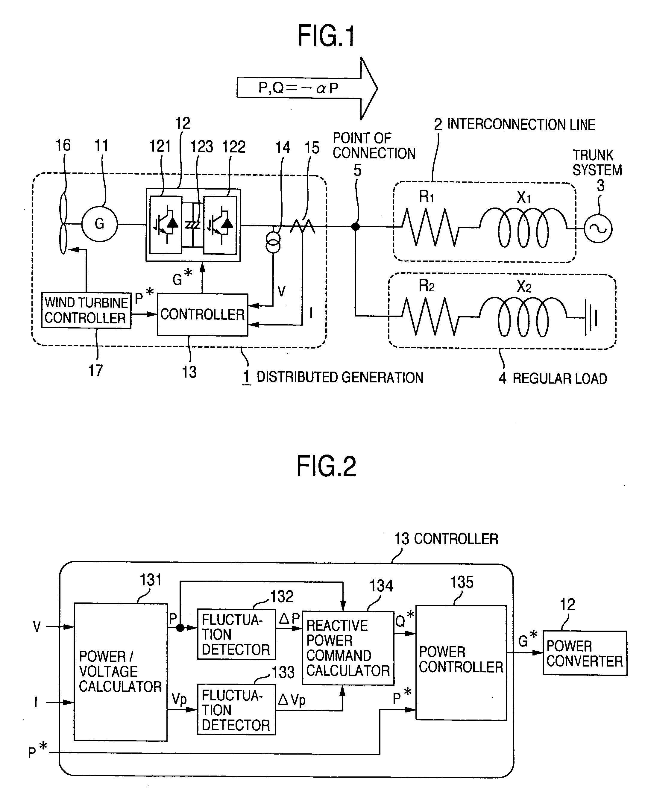
[0034] In this embodiment, a wind turbine generator system serves as the distributed generator 1. The distributed generator 1 comprises a power generator 11, a power converter 12, a controller 13, a voltage detector 14 and a current detector 15. Th...

embodiment 2

[0064]FIG. 10 schematically shows the structure of a reactive power command calculator 134a which includes the calculation of a parameter α(t) for a distributed generation system provided with a power system stabilizing apparatus according to the second embodiment of this invention. FIG. 10 is used here in place of FIG. 6. This second embodiment differs from the first embodiment in the manner that the reactive power command Q* is generated.

[0065] The voltage amplitude Vp at the point 5 of connection fluctuates in response to the fluctuation ΔP of the active power P generated by the distributed generation 1. Apparatuses belonging to the power system, such as SVRs (series voltage regulators), transformers, power generators, SVCs (static var compensators), etc. can control the long period component of the voltage amplitude fluctuation in such a manner that the extent of that fluctuation may fall within a predetermined range. In this case, therefore, the distributed generation has only...

embodiment 3

[0071]FIG. 11 schematically shows the structure of a reactive power command calculator 134b which includes the calculation of a parameter α(t) for a distributed generation system provided with a power system stabilizing apparatus, according to the third embodiment of this invention. FIG. 11 is used here in place of FIG. 6 or FIG. 10. This third embodiment differs from the first and second embodiments in the manner that the reactive power command Q* is generated.

[0072] To begin with, to obtain the parameter α(t), let a selector 1342 choose zero (0) as its output and the reactive power command calculator 134b issues a zero reactive power command, i.e. Q*=0. Under this condition, the distributed generation 1 starts operating with its output reactive power Q equal to 0. Now, the system voltage fluctuation ΔVp1 due to the active power fluctuation ΔP is fed to a rotational coordinate transformer 1343 shown in FIG. 11 so as to be subjected to coordinate transformation. Coordinate transfor...


PUM


Abstract

A distributed generation system that can suppress a voltage fluctuation caused by a distributed generation by an apparatus of a small power capacity in the distributed generation itself and stabilize the power system voltage without inserting interharmonic voltage or current into the power system and without interference among a plurality of distributed generations. Parameter α(t) varying with time is estimated based on fluctuating component ΔP of the active power P generated by the distributed generation and the voltage fluctuating component ΔV attributable to the distributed generation developed at the point of connection between the distributed generation and power system. The distributed generation produces reactive power Q=−αP or Q=−αΔP, to thereby suppresses only the voltage fluctuation of the power system attributable to the distributed generation.

Description

BACKGROUND OF THE INVENTION [0001] This invention relates to a distributed generation system for stabilizing a power system by suppressing the voltage fluctuation in the power system and a method of stabilizing the power system. [0002] In a power distribution system with which a distributed generation such as a wind turbine is connected, it is generally necessary to suppress the voltage fluctuation caused in the power distribution system due to the fluctuations in the output of a distributed generation or in a load connected with the power distribution system. [0003] JP-A-2000-333373 discloses a method of compensating the fluctuations in the system voltage by a distributed generation connected with the system. Namely, in this patent document, there is disclosed a method wherein the system voltage and the system current are detected; the reactive current command for the distributed generation is generated on the basis of the detected system voltage and current; and the voltage on the...

Claims


Application Information

Patent Timeline
Patent Type & Authority Applications(United States)
IPC IPC(8): H02H7/06
CPCH02J3/24H02J3/386Y02E10/763H02J2300/28H02J3/381Y02E10/76H02J3/48H02J3/50
Inventor OOHARA, SHINYAICHINOSE, MASAYAFUTAMI, MOTOOMATSUTAKE, MITSUGUFUKUDA, SHOJI
Owner HITACHI LTD
Why Eureka
Try Eureka