High power, end pumped laser with off-peak pumping

a laser system and laser pump technology, applied in laser details, laser optical devices, semiconductor lasers, etc., can solve the problems of system generating output power levels in excess of several hundred watts that are difficult to meet the requirements of laser operation, system generating such high-powers only at the expense of beam quality, etc., and achieves easy production of over 100 watts output power. , the effect of high quality

Inactive Publication Date: 2007-05-03
LASERSCOPE
View PDF23 Cites 24 Cited by
  • Summary
  • Abstract
  • Description
  • Claims
  • Application Information

AI Technical Summary

Benefits of technology

[0010] A high quality laser easily producing over 100 Watts output power is provided using a laser configuration, described herein, based on a solid-state gain medium, a source of pump energy which is detuned from the maximum absorption wavelength for the gain medium, and optics arranged to deliver the pump energy through an end of the gain medium to propagate along the length of the gain medium.
[0016] The laser configuration described herein is suitable for generation of more than 100 Watts of output at 532 nanometers using an Nd:YAG gain medium and diode laser pumping source. The configuration is stable, easily manufactured and low-cost.
[0017] In summary, an end-pumped high-power laser is described which produces a low M2 beam with stable output power. Output powers greater than 100 and even greater than 1000 Watts can be produced using solid-state hosts and diode laser pump sources. The laser configuration supports efficient intra-cavity frequency conversion.

Problems solved by technology

However, systems generating output power levels in excess of several hundred Watts become very complex.
Also, some systems generate such high-powers only at the expense of beam quality.
However, many solid-state media exhibit thermal lensing or other problems causing aberrations in output beam.
Other systems create complex optics for filling a gain medium with pump energy.
Side-pumping is relatively inefficient; so that the conversion of pump energy into laser output is low at relatively high pump energies.
However, an upper limit is quickly reached for end-pumped gain media, where rapid absorption of pump energy in a small volume within the first few millimeters of the gain media causes thermal fracture.

Method used


Image

  • High power, end pumped laser with off-peak pumping
  • High power, end pumped laser with off-peak pumping
  • High power, end pumped laser with off-peak pumping

Examples


Embodiment Construction

[0025] A detailed description of embodiments of the present invention is provided with reference to the FIGS. 1-6.

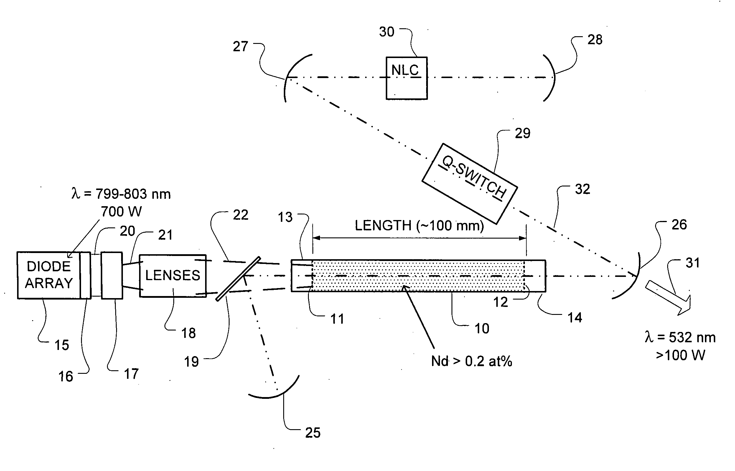
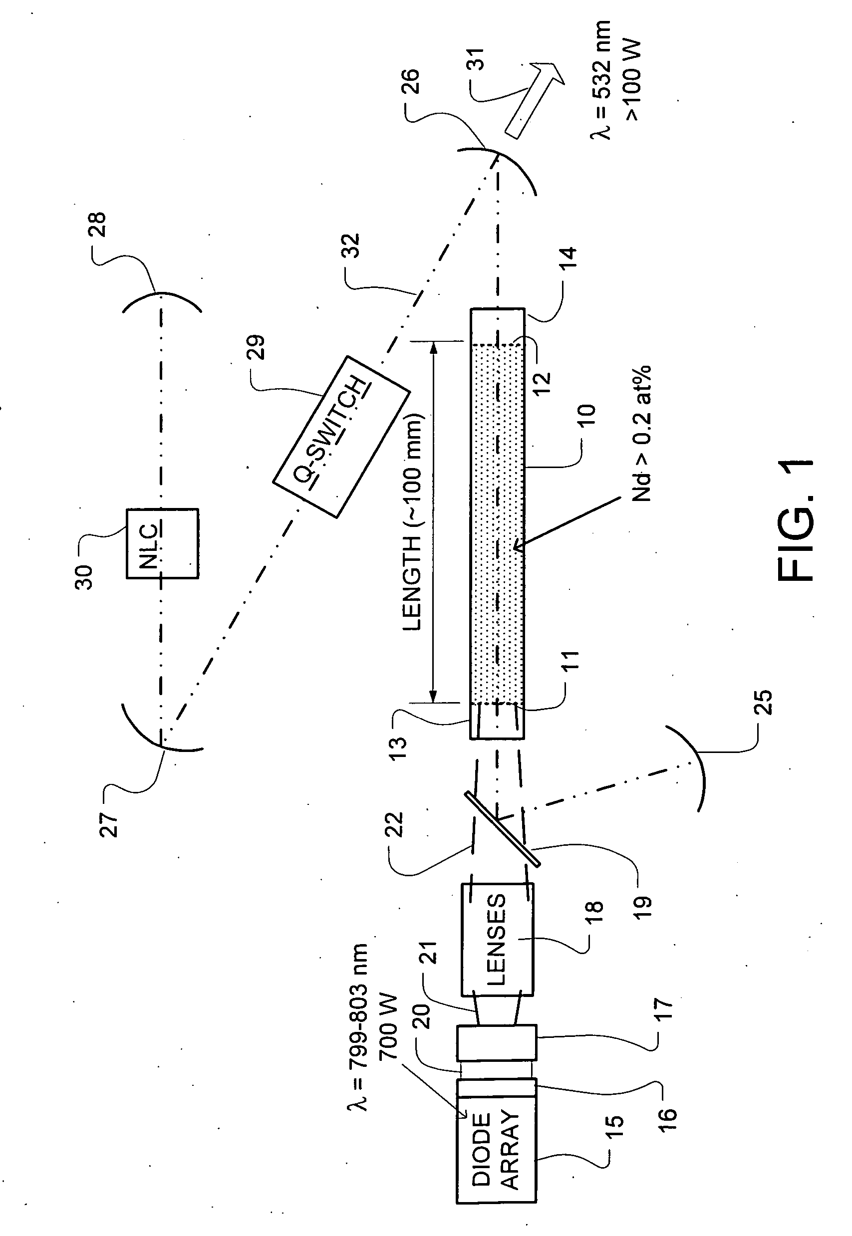
[0026]FIG. 1 illustrates a high-power laser system comprising a gain medium 10 that includes a doped crystalline host, having a first end 11 and a second end 12. The gain medium 10 in a representative embodiment comprises Nd:YAG having a length of about 100 millimeters and a diameter of about 4.5 millimeters. The gain medium 10 is water cooled in exemplary embodiments, along the sides of the host. Undoped endcap 13 about 10 millimeters long in this example, is bonded on the first end 11 of the gain medium 10, and undoped endcap 14 also about 10 millimeters long in this example, is bonded on the second end 12 of the gain medium 10.

[0027] In the high-power end-pumped configuration shown, the undoped endcap 13 can be diffusion bonded but preferably grown on at least the first end 11. In embodiments where significant pump energy reaches the second end of the host 10, anoth...


PUM


Abstract

A laser configuration producing up to 100's of Watts of output is provided, based on a solid-state gain medium, a source of pump energy which is detuned from the maximum absorption wavelength for the gain medium, and optics arranged to deliver the pump energy through an end of the gain medium to propagate along the length of the gain medium. The length of the gain medium and the doping concentration in the gain medium are sufficient the absorption length is on the order of 10's of millimeters, and more than ⅓ of the length, and that 90 percent or more of the pump energy is absorbed within two or fewer passes of the gain medium. A pump energy source that supplies 100 Watts to 1000 Watts or more.

Description

BACKGROUND OF THE INVENTION [0001] 1. Field of the Invention [0002] The present invention relates to laser systems, and more particularly to high-power, end-pumped laser systems with solid-state gain media. [0003] 2. Description of Related Art [0004] High power laser output is desired over a broad range of wavelengths and disciplines throughout the scientific, industrial and medical fields. Many systems have been developed to generate high-power. However, systems generating output power levels in excess of several hundred Watts become very complex. Also, some systems generate such high-powers only at the expense of beam quality. [0005] In solid-state systems, in order to generate a higher output powers, the amount of energy used for pumping the gain medium is increased. However, many solid-state media exhibit thermal lensing or other problems causing aberrations in output beam. The pump energy can be applied from the side of the gain medium, known as a side-pumping, or from the end ...

Claims


Application Information

Patent Timeline
Patent Type & Authority Applications(United States)
IPC IPC(8): H01S3/11
CPCH01S3/005H01S3/061H01S3/0612H01S3/0621H01S3/08072H01S3/0809H01S5/405H01S3/094084H01S3/09415H01S3/109H01S3/11H01S3/1611H01S3/1643H01S3/0817H01S3/1123
Inventor MITCHELL, GERALD
Owner LASERSCOPE
Why Eureka
Try Eureka