Densely woven quasi-unidirectional fabric for ballistic applications

a quasi-unidirectional fabric and dense weaving technology, applied in weaving, protective fabrics, knitting, etc., can solve the problems of easy penetration of armor layers, excessive interstices between yarns, and material not widely accepted in the ballistic field

Inactive Publication Date: 2007-05-03
BARRDAY
View PDF27 Cites 43 Cited by
  • Summary
  • Abstract
  • Description
  • Claims
  • Application Information

AI Technical Summary

Problems solved by technology

It is understood that the material was not widely accepted in the ballistic market.
Without flat, spread yarns, the interstices between the yarns become excessive and a bullet is able to slide through the resultant openings during impact, easily penetrating the layers of the armor.
However, there is a limit to the openness of the weave that can be achieved with a standard woven fabric.
As the openness increases, the fabric tends to become more of a mesh or scrim than a fabric, and such fabric has no merit or value in an armor application.
In addition, the fabric becomes so flimsy that it can not be handled or cut without distorting the orientation of the yarns and ruining the fabric.
The result is that the yarn is prematurely broken, before the maximum amount of energy can be absorbed along its length.
This reduced area of the projectile has a further negative effect on the ballistic performance of the fabric system by restricting the number of yarns than can be behind the deformable projectile.
The use of some unidirectional fabrics has resulted in significant decreases in the weight of some vest or armor systems.
However, the cost of producing the known successful unidirectional fabrics is significantly more than that of a woven fabric.
The increased cost is mainly due to the requirement that the individual layers of the fabric be produced in one weaving or prepreg operation and cross-plied in a second operation to produce a 0 / 90 construction.

Method used


Image

  • Densely woven quasi-unidirectional fabric for ballistic applications
  • Densely woven quasi-unidirectional fabric for ballistic applications
  • Densely woven quasi-unidirectional fabric for ballistic applications

Examples


example i

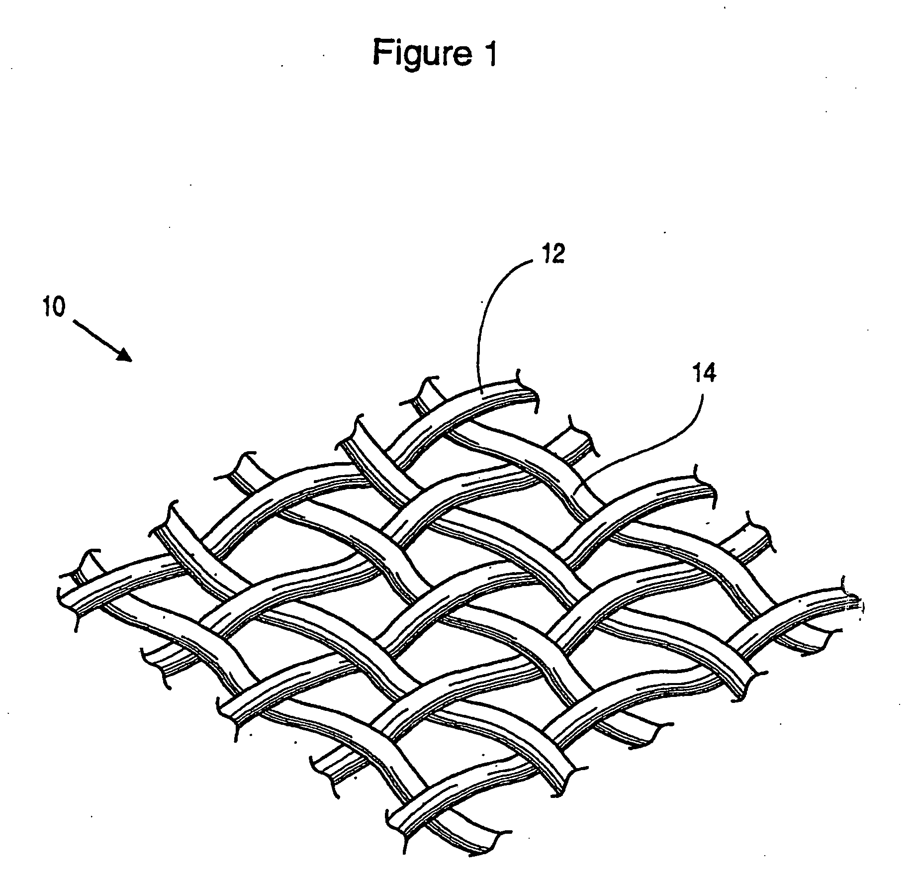
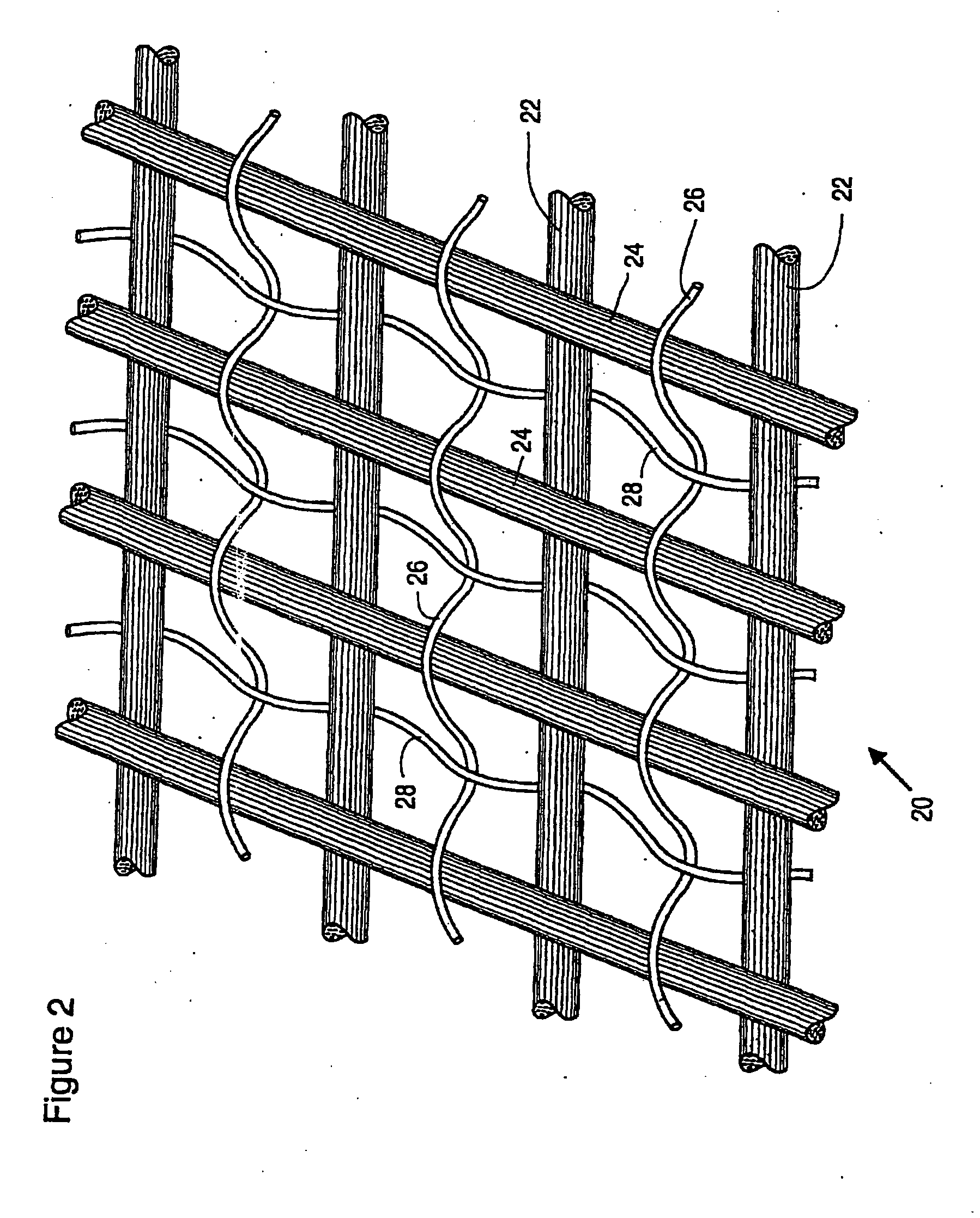
[0093] An experimental fabric was made with 1330 dtex (i.e., 1,200 denier) Spectra® (extended chain polyethylene) warp and fill yarns and 78 dtex nylon warp and fill yarns. The Spectra® yarn was twisted while the nylon yarn was not twisted. The Spectra® yarn was fed into the loom from one beam while the nylon was fed from a second beam.

[0094] The different warp yarns were alternated in the fabric, i.e. a Spectra® yarn followed by a nylon yarn, repeated across the fabric. The fill yarn was also alternately Spectra® and nylon. The fabric was woven as a plain weave fabric. To reflect the difference in strength, modulus and diameter, the Spectra yarns were unidirectional while the nylon yarns formed a crimped fabric supporting the Spectra yarns. The count of the fabric was 21 Spectra per inch and 21 nylon yarns per Inch in both the warp and fill direction. The maximum number of 1200 denier yarns that can be woven into a plain weave is 25 ends per inch. The ratio of the diameter of the ...

example ii

[0097] An experimental fabric was made with 1330 dtex Spectra® warp and fill yarns and 78 dtex nylon warp and fill yarns. The Spectra yarn was twisted while the nylon yarn was not twisted. The Spectra® yarn was fed into the loom from one beam while the nylon was fed from a second beam.

[0098] The different warp yarns were alternated in the fabric, i.e. a Spectra® yarn followed by a nylon yarn, repeated across the fabric. The fill yarn was also alternately Spectra® and nylon. The fabric was woven as a plain weave fabric. To reflect the difference in strength, modulus and diameter, the Spectra® yarns were unidirectional while the nylon yarns formed a crimped fabric supporting the Spectra® yarns. The count of the fabric was 16 Spectra per inch and 16 nylon yarns per inch in both the warp and fill direction. The maximum number of 1200 denier yarns that can be woven into a plain weave is 25 ends per inch. The ratio of the diameter of the encapsulating yarn to the ballistic yarn was 5.4%....

example iii

[0100] A fabric was made with 1330 dtex Spectra® warp and fill yarns and 78 dtex nylon warp and fill yarns. The Spectra® yarn was twisted while the nylon yarn was not twisted. The Spectra® yarn was fed into the loom from one beam while the nylon was fed from a second beam. The different warp yarns were alternated in the fabric, i.e. a Spectra® yarn followed by a nylon yarn, repeated across the fabric. The fill yarn was also alternately Spectra® and nylon. The fabric was woven as a plain weave fabric. To reflect the difference in strength, modulus and diameter, the Spectra® yarns were unidirectional while the nylon yarns formed a crimped fabric supporting the Spectra® yarns. The count of the fabric was 10.5 Spectra® per inch and 10.5 nylon yarns per inch in both the warp and fill direction. The maximum number of 1200 denier yarns that can be woven into a plain weave is 25 ends per inch. The ratio of the diameter of the encapsulating yarn to the ballistic yarn was 5.4%. The finished f...


PUM

PropertyMeasurementUnit
linear densityaaaaaaaaaa
elongationaaaaaaaaaa

Abstract

A fabric including a first layer of high-performance unidirectional yarns and a second layer of high-performance unidirectional yarns disposed transversely to the first layer. The fabric also includes warp and fill encapsulating yarns woven around the unidirectional yarns to substantially stabilize the unidirectional yarns. The encapsulating yarns have tenacities and tensile moduli substantially less than the tenacities and tensile moduli of the unidirectional yarns. The fabric has a cover factor between approximately 0.75 and approximately 1.50.

Description

REFERENCE TO RELATED APPLICATION [0001] This application is a continuation-in-part of application Ser. No. 10 / 476,226, filed on Jun. 3, 2004, and hereby claims priority thereto and incorporates such application in its entirety by reference. Application Ser. No. 10 / 476,226 is the U.S. national stage filing of PCT Application No. PCT / CA02 / 00655, filed on May 1, 2002, which claims priority to U.S. Provisional Application No. 60 / 288,568, filed on May 3, 2001. This application hereby claims priority to all such applications and incorporates each in its entirety by reference.FIELD OF THE INVENTION [0002] This invention is related to densely woven quasi-unidirectional fabric for ballistic applications, and in particular, for use in composite materials having rigid matrices. BACKGROUND TO THE INVENTION [0003] Unidirectional fabrics are fabrics in which the warp and weft yarns are substantially parallel and in the plane of the fabric but without the over and under crimp of a woven structure....

Claims


Application Information

Patent Timeline
Patent Type & Authority Applications(United States)
IPC IPC(8): B32B27/12B32B27/04B32B5/12F41H5/04
CPCD03D1/0052D03D15/0016D03D15/02D03D25/005D04B21/16Y10T428/24058D10B2401/063F41H5/0485Y10S428/911Y10T428/24132Y10T428/24174D10B2331/021Y10T442/2762Y10T442/2861Y10T442/2615Y10T442/2623Y10T442/2992D03D15/247D03D15/593
Inventor HEERDEN, JASON VANSHAHKARAMI, SHEKOUFEHCUNNINGHAM, DAVID VERLINPRITCHARD, LAURA E.
Owner BARRDAY
Why Eureka
Try Eureka