IV catheter with in-line valve and methods related thereto

a technology of iv catheter and in-line valve, which is applied in the field of medical infusion or access devices, can solve the problems of increased infection risk, significant discomfort for patients, and ineffective efforts, and achieve the effect of facilitating the axial movement of the ring member

Active Publication Date: 2007-05-03
KPR U S LLC
View PDF39 Cites 50 Cited by
  • Summary
  • Abstract
  • Description
  • Claims
  • Application Information

AI Technical Summary

Benefits of technology

[0031] In more particular illustrative embodiments, the rib is configured so as to have a distal side surface extending in a distal direction, the distal side surface being a sloped surface. In further embodiments, the rib includes a proximal side surface having a first portion that is substantially parallel to the vertical surface of the lip and having a second portion that slopes upwardly and distally from the first portion to the top of the rib. The sloped distal side surface and the sloped proximal side surface second portion, among other things facilitate axial movement of the ring member during the insertion process.

Problems solved by technology

While efforts are undertaken in this approach to prevent blood flow back through the catheter tube, such efforts are typically not completely effective and some blood flows onto the patient, bedding, clothing and the like.
Such an elongate valve is believed to be unstable and tends to deflect or travel in a non-linear manner during use, thus creating an unreliable seal, possibly resulting in leakage.
Valve leakage can create significant discomfort for the patient and increased risk of infection, along with increased risk of exposure to blood borne pathogens for healthcare workers.
Further, the internal cavity of the prior art device has a tendency to collapse during use as a result of the blood pressure of the patient.
This could unseat the valve and produce leakage.
Also, the internal cavity results in significant “dead” space in the flow path, in which blood or liquid can get trapped.
Such trapped fluids can pose a risk of infection and / or thrombosis to the patient.
In addition to the above, an elongate valve results in a longer catheter, which is harder for healthcare workers to use while being more expensive to fabricate.

Method used


Image

  • IV catheter with in-line valve and methods related thereto
  • IV catheter with in-line valve and methods related thereto
  • IV catheter with in-line valve and methods related thereto

Examples


Embodiment Construction

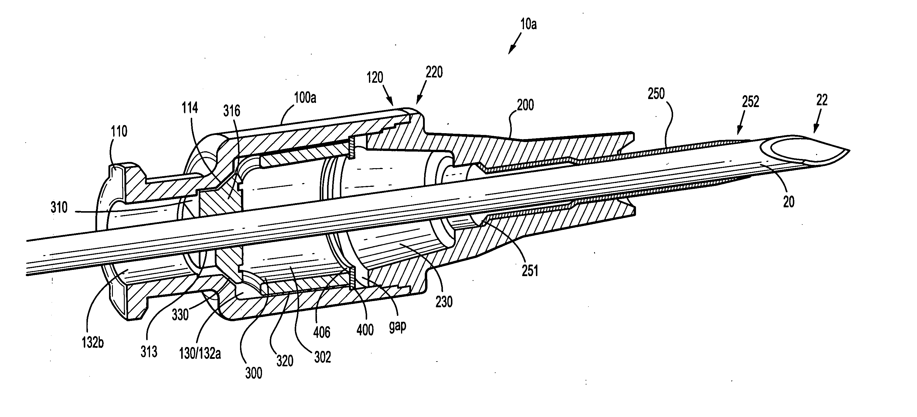
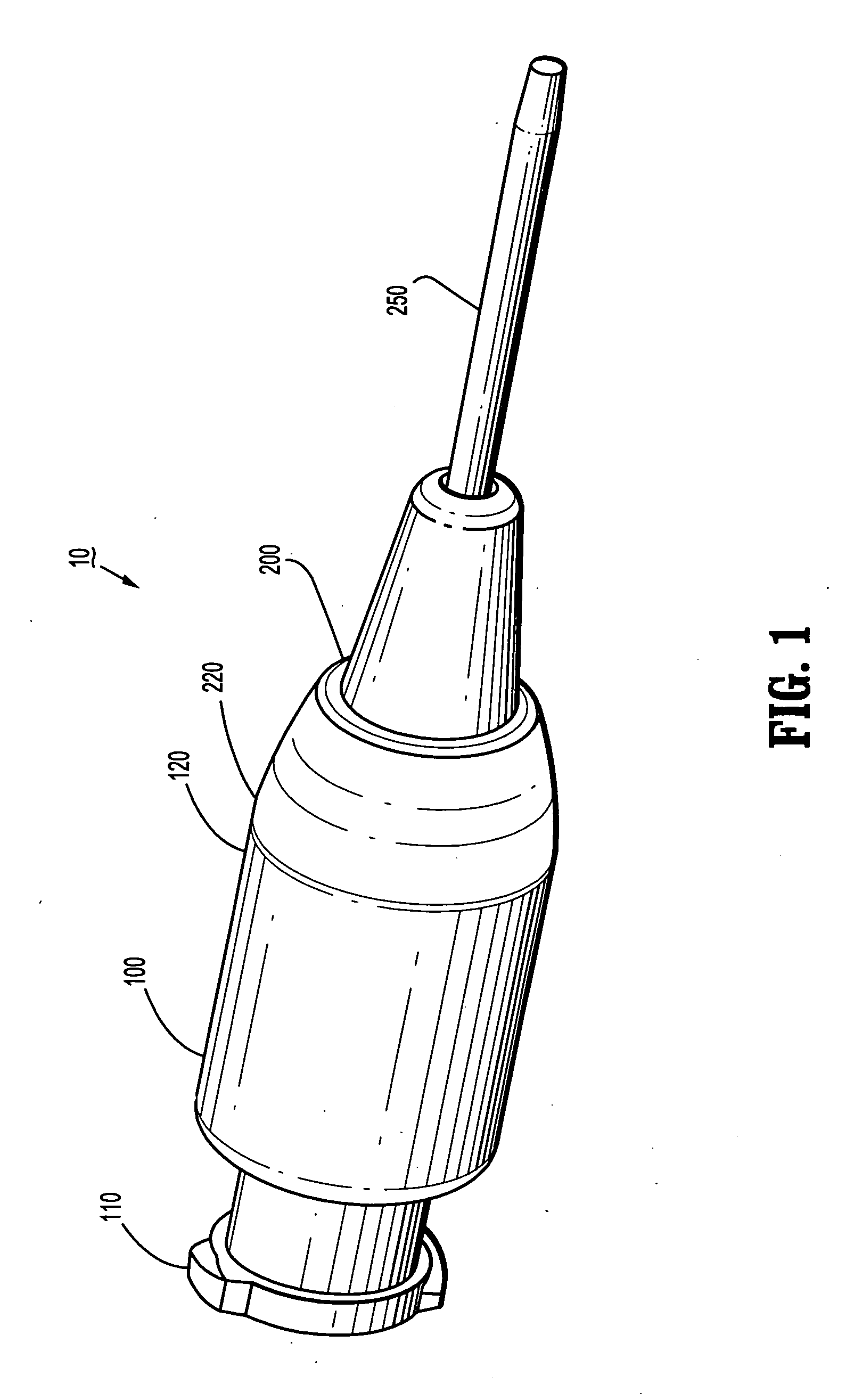
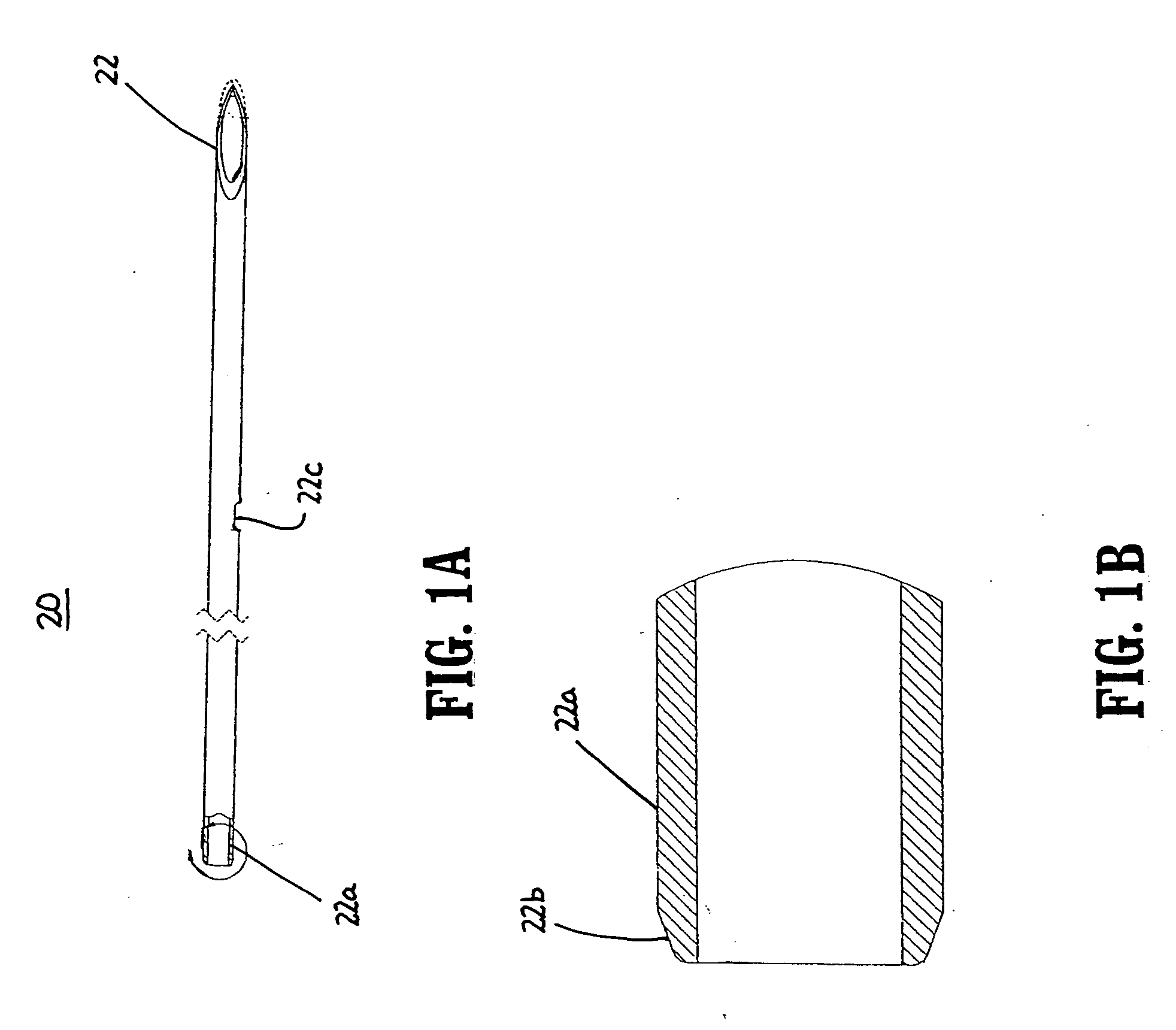
[0073] Referring now to the various figures of the drawing wherein like reference characters refer to like parts, there is shown in FIG. 1 an axonometric view of an in-line valve IV catheter assembly 10 that is of the catheter over stylet / sharp / cannula type of IV catheter. As is more clearly illustrated in FIG. 2A, the stylet / sharp / cannula 20 is inserted through the IV catheter assembly or IV catheter so that the piercing end 22 of the stylet / sharp / cannula 20 extends out of the open end 252 of the catheter tubular member 250. In this way and as known to those skilled in the art, a user inserts the piercing end 22 of the stylet / sharp / cannula 20 through the skin and subcutaneous tissue of the body so that the open end 252 of the tubular member 250 of the IV catheter assembly 10 is disposed within the blood vessel (e.g., vein or artery) of the patient

[0074] Referring to FIGS. 1A and 1B, cannula 20 preferably includes a proximal end 22a opposite distal end or piercing end 22. Proximal ...


PUM

PropertyMeasurementUnit
inner circumferenceaaaaaaaaaa
pressureaaaaaaaaaa
distanceaaaaaaaaaa

Abstract

Featured is a vascular access device such as an IV catheter device including a housing, a tubular member and a seal member, and a securing mechanism. The housing includes a proximal and distal portion and a chamber that extends between the proximal and distal portions. The tubular member is coupled to the housing distal portion so it is fluidly coupled to the chamber. The seal member is disposed within the chamber and the securing mechanism secures the seal member distal end to the housing proximal portion so the seal member is sealingly and compressibly retained between a chamber proximal end and the securing mechanism. Such a seal member also is constituted so a portion of the seal member moves axially responsive to an axial force applied to the proximal end.

Description

[0001] This application claims priority from U.S. Provisional Application Ser. No. 60 / 840,367, which was filed on Aug. 25, 2006, and from U.S. Provisional Application Ser. No. 60 / 726,026, which was filed on Oct. 11, 2005. The entire contents of each are incorporated herein by reference.FIELD OF INVENTION [0002] The present invention generally relates to medical infusion or access devices such as intravenous (IV) catheters and more particularly to a vascular access device including a valve and more specifically an over-the-needle IV catheter including an in-line valve and having a re-sealable septum. BACKGROUND OF THE INVENTION [0003] Medical access devices, particularly infusion devices, over-the-needle catheters, other catheters and feeding tubes, are important tools for administration of fluids to patients. In the normal management of a catheter or other medical access device after it is placed in a patient, it is often necessary to be able to add or withdraw fluids through the de...

Claims


Application Information

Patent Timeline
Patent Type & Authority Applications(United States)
IPC IPC(8): A61M5/00A61M31/00F16K43/00
CPCA61M39/06A61M39/0606Y10T29/49826A61M2039/062A61M2205/583A61M39/26Y10T137/0491A61M31/00A61M5/00A61M5/16813A61M39/22
Inventor BELLEY, RICHARD A.FISER, RICHARDWEILBACHER, EUGENE E.
Owner KPR U S LLC
Why Eureka
Try Eureka