System and Computer Program Product for Analyzing and Manufacturing a Structural Member Having a Predetermined Load Capacity

a technology of structural components and computer programs, applied in the direction of stochastic cad, instruments, cad techniques, etc., can solve the problems of difficult to accurately predict the failure point of a composite member, difficult to analyze the failure of conventional techniques, and high cost and time consumption of testing

Inactive Publication Date: 2007-05-03
THE BOEING CO
View PDF7 Cites 38 Cited by
  • Summary
  • Abstract
  • Description
  • Claims
  • Application Information

AI Technical Summary

Benefits of technology

[0010] According to one aspect of the invention, an additional executable portion can also be provided for performing a probabilistic analysis of the results data to determine variations in the results data due to probabilistically likely variations in one or more of the materials of the structural member and / or the geometric configuration of the structural member. An additional executable portion can also be provided for adjusting an attribute, such as a dimension of the composite member, according to the calculated load capacity, such that an iterative analysis of the member can be performed automatically.

Problems solved by technology

Composite structural members typically exhibit material properties that make failure analysis by conventional techniques difficult.
Thus, it can be difficult to accurately predict the point of failure of a composite member based on the deformation that results from a stress before the member develops cracks or otherwise begins to fail.
In particular, the anisotropic nature of fiber reinforced composite materials, as well as complexities associated with the use of multiple materials in the same structural component, generally requires predictions based on empirical techniques.
Such testing can be expensive and time consuming, thereby limiting the number of alternative designs for a particular member that can be evaluated.

Method used


Image

  • System and Computer Program Product for Analyzing and Manufacturing a Structural Member Having a Predetermined Load Capacity
  • System and Computer Program Product for Analyzing and Manufacturing a Structural Member Having a Predetermined Load Capacity
  • System and Computer Program Product for Analyzing and Manufacturing a Structural Member Having a Predetermined Load Capacity

Examples


Embodiment Construction

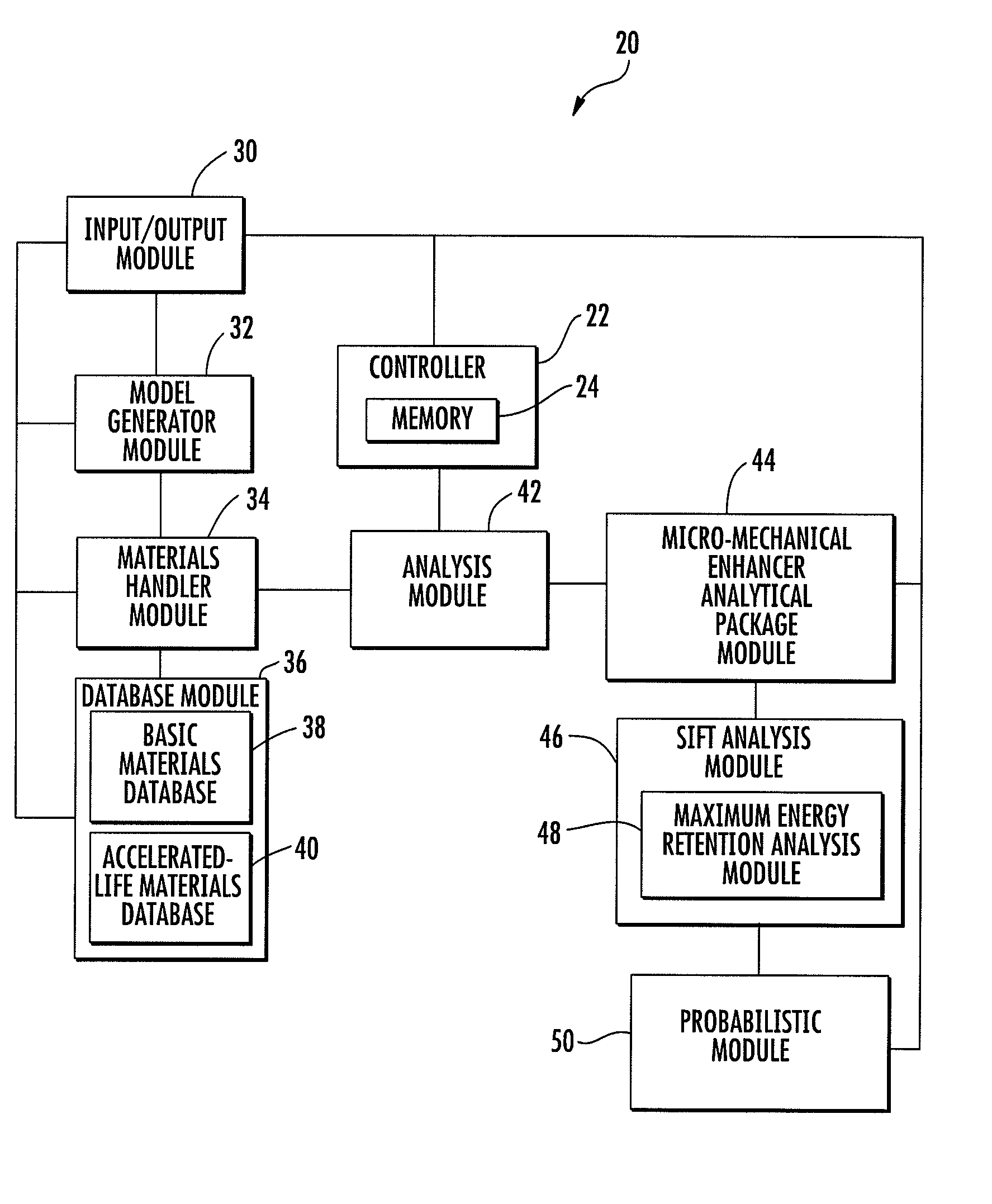
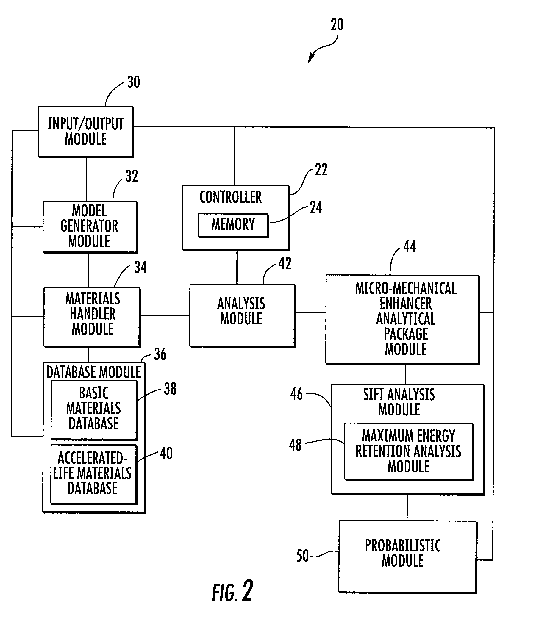
[0016] The present invention now will be described more fully hereinafter with reference to the accompanying drawings, in which some, but not all embodiments of the invention are shown. This invention may be embodied in many different forms and should not be construed as limited to the embodiments set forth herein; rather, these embodiments are provided so that this disclosure will be thorough and complete, and will fully convey the scope of the invention to those skilled in the art. Like numbers refer to like elements throughout.

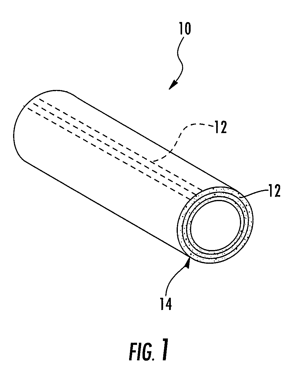
[0017] Referring now to the drawings, and in particular to FIG. 1, there is shown a structural member 10 formed of a composite material according to one embodiment of the present invention. In particular, the composite material of the member 10 includes a fiber phase and a matrix phase. The fiber phase is defined by a plurality of fiber reinforcement members 12 (three of which are illustrated by broken lines extending longitudinally along the member 10 in ...


PUM


Abstract

A system and computer program product for analyzing a load capacity of a composite member are provided. The system includes devices or modules for receiving model data that is characteristic of a configuration and load condition of a structural member and material data that is characteristic of material properties of a material of the structural member. The model data is analyzed to generate analysis data including strain tensors for a plurality of nodes of the structural member. Enhanced analysis data is generated, including a critical strain invariant value representative of a material of the structural member. The enhanced analysis data is further analyzed according to a strain invariant failure theory to generate results data representative of load conditions that result in damage instability in the structural member and a likely location, direction, and / or path of progression of the instability.

Description

CROSS REFERENCE TO RELATED APPLICATIONS [0001] This application is related to commonly owned copending Provisional Application Ser. No. 60 / 733,102, filed Nov. 3, 2005, incorporated herein by reference in its entirety, and claims the benefit of its earlier filing date under 35 U.S.C. 119(e).BACKGROUND OF THE INVENTION [0002] 1. Field of the Invention [0003] The present invention relates generally to systems and computer program products for analyzing and / or manufacturing a structural member with a predetermined load capacity, such as by determining the critical load of a composite member, e.g., according to a partitioning of strain energy and the criticality of gauss point strains for one or more predetermined loads. [0004] 2. Description of Related Art [0005] Composite structural members typically exhibit material properties that make failure analysis by conventional techniques difficult. For example, many composite materials exhibit little deformation before cracking or otherwise f...

Claims


Application Information

Patent Timeline
Patent Type & Authority Applications(United States)
IPC IPC(8): G01B3/44
CPCG06F17/5018G06F2217/10G06F2217/44G06F30/23G06F2111/08G06F2113/26
Inventor GOSSE, JONATHAN H.WOLLSCHLAGER, JEFFREY A.
Owner THE BOEING CO
Why Eureka
Try Eureka