Device and method of controlling hydraulic drive of construction machinery

a technology of hydraulic drive and control device, which is applied in the direction of electrical control, positive displacement liquid engine, fluid coupling, etc., can solve the problems of decreasing operability, achieve stable stable operation speed or drive torque of work machine, and achieve stable operation speed or drive torque

Active Publication Date: 2007-05-10
KOMATSU LTD
View PDF1 Cites 56 Cited by
  • Summary
  • Abstract
  • Description
  • Claims
  • Application Information

AI Technical Summary

Benefits of technology

[0008] In one preferred mode for carrying out the invention, the controller determines the engine output torque control line and the pump torque control line so that an engine revolution speed at a matching point of the determined engine output torque control line and the determined pump torque control line assumes a substantially constant predetermined value for any identified operation mode, when the identified operation mode corresponds to any of a plurality of predetermined operation modes. As a result, the engine revolution speed is maintained at a substantially constant level and, therefore, the operation speed of the work machine is stable, even if the operation mode changes between the plurality of predetermined operation modes.
[0009] In another preferred mode for carrying out the invention, the controller determines the engine output torque control line and the pump torque control line so that a torque at a matching point of the determined engine output torque control line and the determined pump torque control line assumes a substantially constant predetermined value for any identified operation mode, when the identified operation mode corresponds to any of a plurality of predetermined operation modes. As a result, the output torque from the engine to the work machine is maintained at a substantially constant level and, therefore, the drive torque of the work machine is stable, even if the operation mode changes between the plurality of predetermined operation modes.
[0010] In yet another preferred mode for carrying out the invention, the controller determines a pump absorption horsepower according to the identified operation mode so that different pump absorption horsepower is designated for different operation modes, and controls the output torque of the engine by using the equal horsepower line of the determined pump absorption horsepower as the engine output torque control line. By adequately determining the pump absorption horsepower according to the operation mode, the operation speed or drive torque of the work machine can be stabilized even if the operation mode cha...

Problems solved by technology

The resultant problem is that the operation rate or drive torque (for example, an excavation force) of the work machi...

Method used


Image

  • Device and method of controlling hydraulic drive of construction machinery
  • Device and method of controlling hydraulic drive of construction machinery
  • Device and method of controlling hydraulic drive of construction machinery

Examples


Embodiment Construction

[0023] An embodiment of the device for controlling hydraulic drive in accordance with the present invention will be described below with reference to the appended drawings.

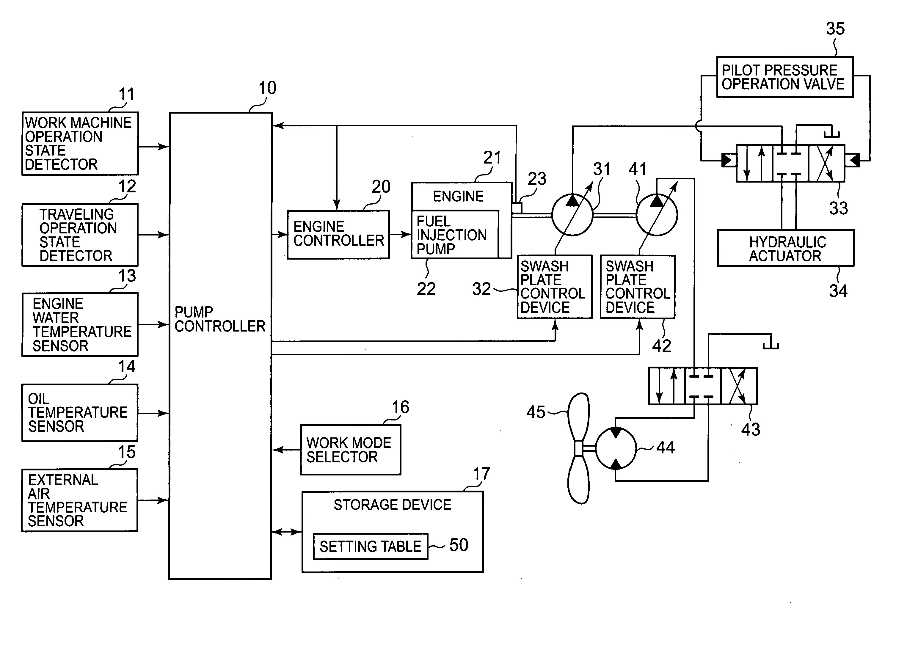
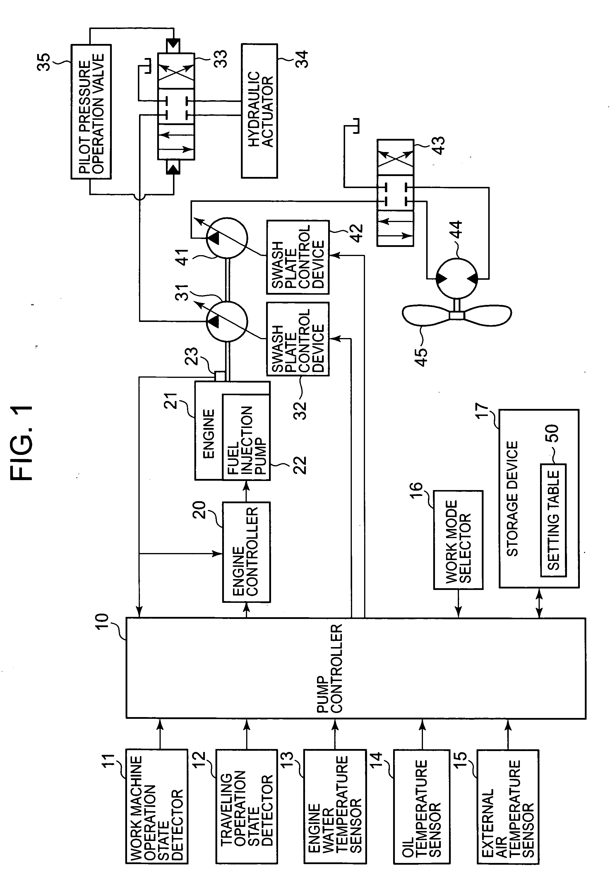
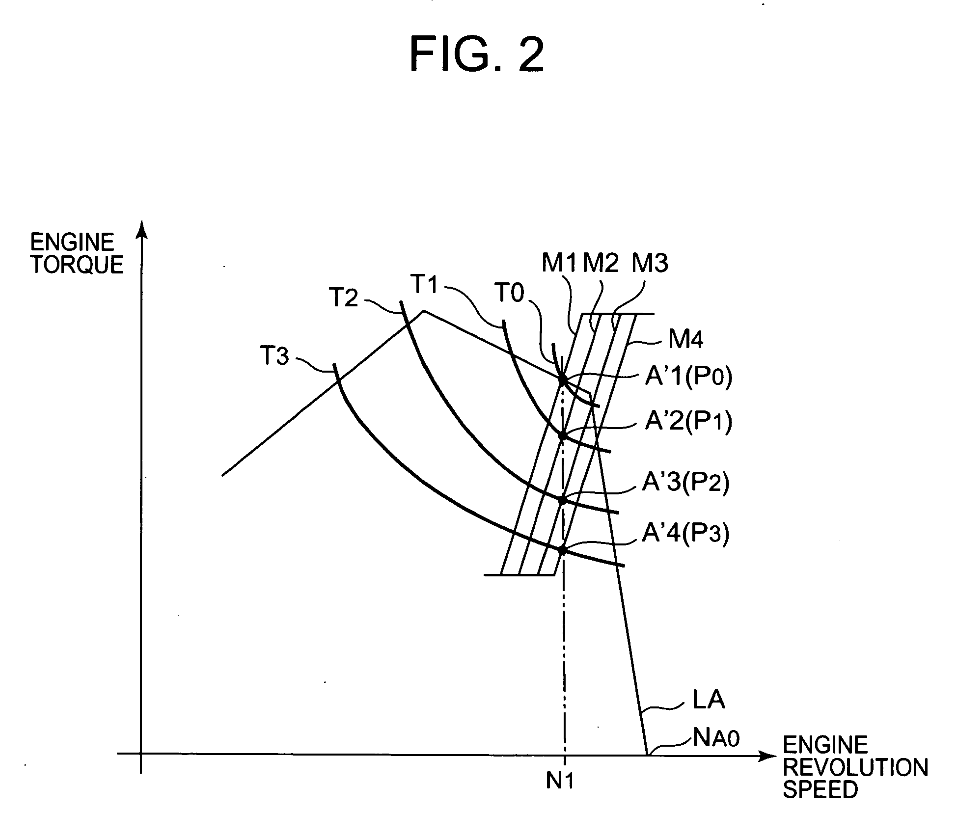
[0024]FIG. 1 is a block diagram illustrating the hardware structure of an embodiment of the hydraulic control device in accordance with the present invention. FIG. 2 is an explanatory drawing of engine output characteristic and a pump absorption torque characteristic that illustrate the operation of the hydraulic control device. First, the hardware structure will be explained with reference to FIG. 1 and FIG. 2. Here, the explanation will be conducted with reference to a hydraulic shovel as an example of a construction machine using the present invention.

[0025] As shown in FIG. 1, a hydraulic pump 31 for a work machine and a hydraulic pump 41 for an auxiliary device are linked via a power take-off device (not shown in the figure) to an output shaft of an engine 21. The oil discharged under pressure from the hydr...


PUM


Abstract

In construction machinery, control is conducted to keep a work machine to operate at a constant speed regardless of the operation thereof. Different engine output lines T0-T3 and pump torque lines M1-M4 are defined for different operation types. All the matching points of the engine output lines T0-T3 and pump torque lines M1-M4 designate a constant engine speed N1. One engine output line and one pump torque line are selected according to the operation type presently selected. An output horsepower of the engine is controlled on an equal horsepower line corresponding to a sum of a horsepower for an auxiliary machine and a horsepower at a matching point of the selected lines. The pump torque for the work machine is controlled on the selected pump torque line. The engine operates at a constant speed N1 even when the operation type varies or the horsepower for the auxiliary machine changes.

Description

TECHNICAL FIELD [0001] The present invention relates to a hydraulic drive control device and method for controlling a hydraulic drive system of construction machinery such as a hydraulic shovel. BACKGROUND ART [0002] In construction machinery in which a plurality of work machines (for example, an arm, a bucket, a boom, a turret device, and a travel device of a hydraulic shovel) and auxiliary machines (for example, an engine cooling fan) are driven by the oil supplied under pressure from a plurality of hydraulic pumps driven by an engine, the process of setting the engine output characteristic (revolution speed and output torque) according to a selected work mode, controlling the total absorption torque (a product of discharge quantities of oil per one revolution and oil pressures)of the plural hydraulic pumps so as to obtain the predetermined characteristic, and controlling the operation point of the engine to a matching point of the output torque of the engine and the absorption to...

Claims


Application Information

Patent Timeline
IPC IPC(8): F16D31/02E02F9/22F02D29/02F02D31/00F02D41/24F04B49/06
CPCE02F9/2235E02F9/2246E02F9/2292E02F9/2296F02D29/02F02D31/007F02D41/2422F02D2250/18F04B49/065
Inventor OHIGASHI, KOJIKAWAKAMI, TAKASHIKIMOTO, KENZO
Owner KOMATSU LTD
Why Eureka
Try Eureka