Radar level gauge with variable transmission power

a technology of radar level gauges and transmission power, which is applied in the direction of level indicators by physical variable measurement, liquid/fluent solid measurement, engine lubrication, etc., can solve the problem of imperfect utilization of the dynamic range of the a/d-converter, the signal-to-noise ratio of the tank signal is not improved, and the received signal and any noise are equal. the effect of improving the utilization of the dynamic rang

Active Publication Date: 2007-05-10
ROSEMOUNT TANK RADAR
View PDF7 Cites 42 Cited by
  • Summary
  • Abstract
  • Description
  • Claims
  • Application Information

AI Technical Summary

Benefits of technology

[0009] It is an object with the present invention to at least partly overcome at least one of the above problems, and to provide a radar level gauge having an improved utilization of the dynamic range of the A / D-converter.

Problems solved by technology

A drawback with the above described solution is that the received signal and any noise are amplified an equal amount.
Therefore, the signal-to-noise ratio of the tank signal is not improved, and leads to an imperfect utilization of the dynamic range of the A / D-converter.
An additional drawback is that the linear gain function on the receiver side will distort the tank signal, as the rising edge and falling edge of a peak will be amplified with different gains.
Such distortions can lead to erroneous determination of the peak location, and must be compensated for later on in the processing, leading to more complex processing.
Yet another drawback is that the gain function cannot compensate for variations in the actual conditions in the tank.

Method used


Image

  • Radar level gauge with variable transmission power
  • Radar level gauge with variable transmission power
  • Radar level gauge with variable transmission power

Examples


Embodiment Construction

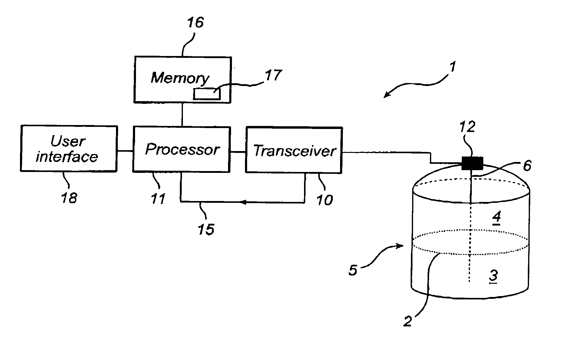
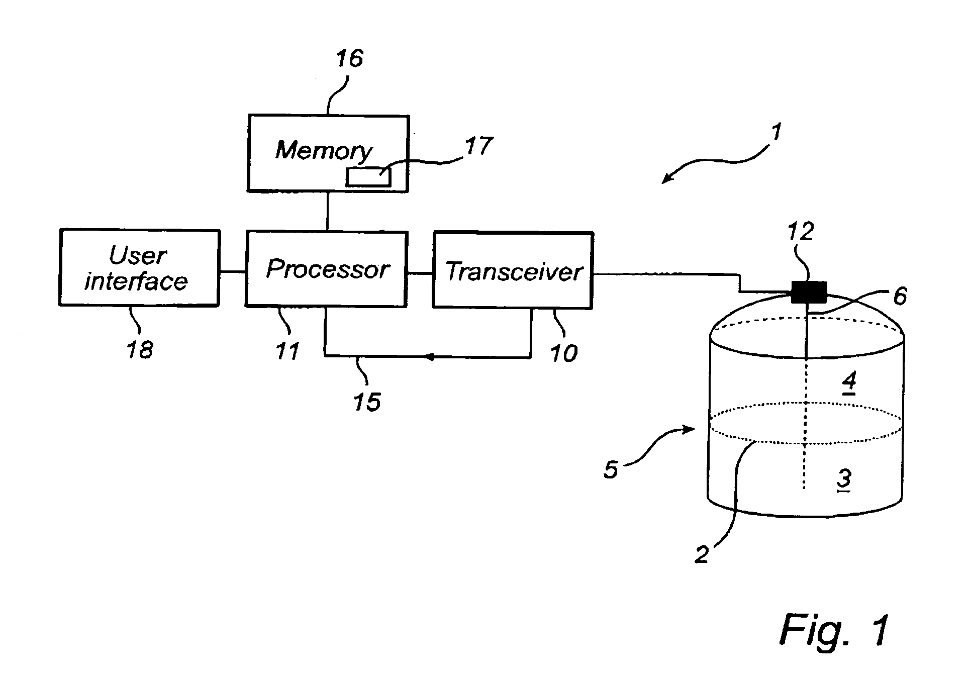
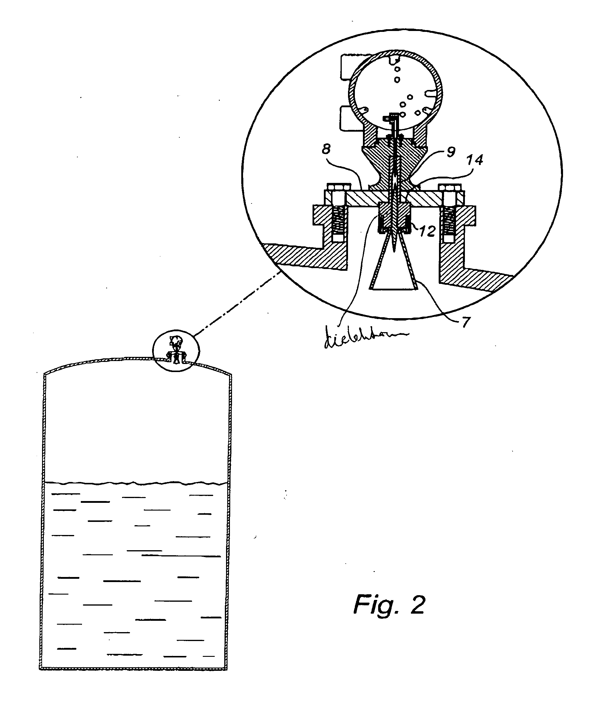
[0030]FIGS. 1 and 2 schematically show two different types of pulsed radar level gauges (RLG) 1 in which a method according to the invention may be advantageously used.

[0031] In both figures, the RLG 1 is arranged to perform measurements of a process variable in a tank, such as the level of an interface 2 between two (or more) materials 3, 4 in the tank 5. Typically, the first material 3 is a content stored in the tank, e.g. a liquid such as gasoline, while the second material 4 is air or some other atmosphere. In that case, the RLG will enable detection of the level of the surface of the content in the tank. Typically, only the level of a first liquid surface is measured, and / or a second liquid surface if the first liquid is sufficiently transparent.

[0032] In both figures, the RLG 1 comprises a transceiver 10, controlled by a processor 11 to transmit electromagnetic signals to a signal medium interface 12 in the tank 5. The signals can be DC pulses with a length of about 2 ns or ...


PUM


Abstract

A pulsed radar level gauge, comprising a transmitter for generating and transmitting a signal in the form of a pulse train, means for receiving pulses reflected in said tank, and to form an analogue tank signal based on these reflections, an analogue to digital converter for sampling and digitizing said tank signal and forming a digital time domain reflectometry (TDR) signal, and means for varying the output power of said transmitter during the transmission of said pulse train, in order to adjust an amplitude of said analogue tank signal to match the dynamics of said A/D-converter. A gain function applied on the receiver side is thus replaced by varying the output power on the transmitter side. This allows the signal-to-noise ratio to be improved, as the noise will not be amplified together with the signal.

Description

TECHNICAL FIELD [0001] The present invention relates to pulsed radar level gauges used for determining a process variable of a content in a tank. TECHNICAL BACKGROUND [0002] In a conventional pulsed radar level gauge, constant power pulses are transmitted into the tank with a repetition frequency in the range 100 kHz to a few MHz. The pulses can be DC pulses or pulses modulated on a microwave frequency carrier wave. The pulse can be guided by a wave guiding structure into the tank, or be allowed to propagate freely. On the receiver side, a reflection from the interior of the tank is received, and a low frequency analogue tank signal is formed and then digitized to form a digital time domain reflectometry (TDR) signal. [0003] Before the A / D-conversion, the analogue tank signal is amplified, partly with a ramp gain function and partly with a constant gain. The reason for this amplification is to match the received signal to the dynamics of the A / D-converter. [0004] First of all, it is...

Claims


Application Information

Patent Timeline
Patent Type & Authority Applications(United States)
IPC IPC(8): G01F23/00G01F23/28
CPCG01F23/284
Inventor ERIKSSON, MIKAELWENNERBERG, TOMAS
Owner ROSEMOUNT TANK RADAR
Why Eureka
Try Eureka