System and method for circuit compliance compensated pressure-regulated volume control in a patient respiratory ventilator

a technology of circuit compliance compensation and volume control, which is applied in the direction of mechanical equipment, valves, respirators, etc., can solve the problems of inability to achieve precise volume delivery, inability to adjust the setting or approach of many circuit compliance compensation designs or algorithms, and inability to accurately control the volume of the patient respiratory ventilator, etc., to achieve the effect of prolonging the inspiratory time and constant i:e ratio

Active Publication Date: 2007-05-10
VYAIRE MEDICAL 211 INC
View PDF11 Cites 55 Cited by
  • Summary
  • Abstract
  • Description
  • Claims
  • Application Information

AI Technical Summary

Benefits of technology

[0010] A ventilation system that incorporating the above the system for circuit compliance compensated pressure regulated volume control is also provided. The ventilation system includes a ventilator for supplying inspiratory gas to the patient and re-circulating the expiratory gas exhaled from the patient and a patient circuit, preferably a Y-circuit, for providing the flow communication between the ventilator and the patient. Sensors and transducers are provided to measure the inspiratory flow, expiratory flow, pati

Problems solved by technology

Without compensation for the circuit compliance, inaccurate volume delivery and inadequate flow will be delivered to the patient.
Currently, the setting or approaches in many of the circuit compliance compensation designs or algorithms cannot achieve precise volume delivery especially for neonatal patients without the risk of over delivering volume.
Therefore, most of the ventilators available in the market do not allow not allow for circuit compliance compensation designs applied to neonatal patients due to the stringen

Method used


Image

  • System and method for circuit compliance compensated pressure-regulated volume control in a patient respiratory ventilator
  • System and method for circuit compliance compensated pressure-regulated volume control in a patient respiratory ventilator
  • System and method for circuit compliance compensated pressure-regulated volume control in a patient respiratory ventilator

Examples


Embodiment Construction

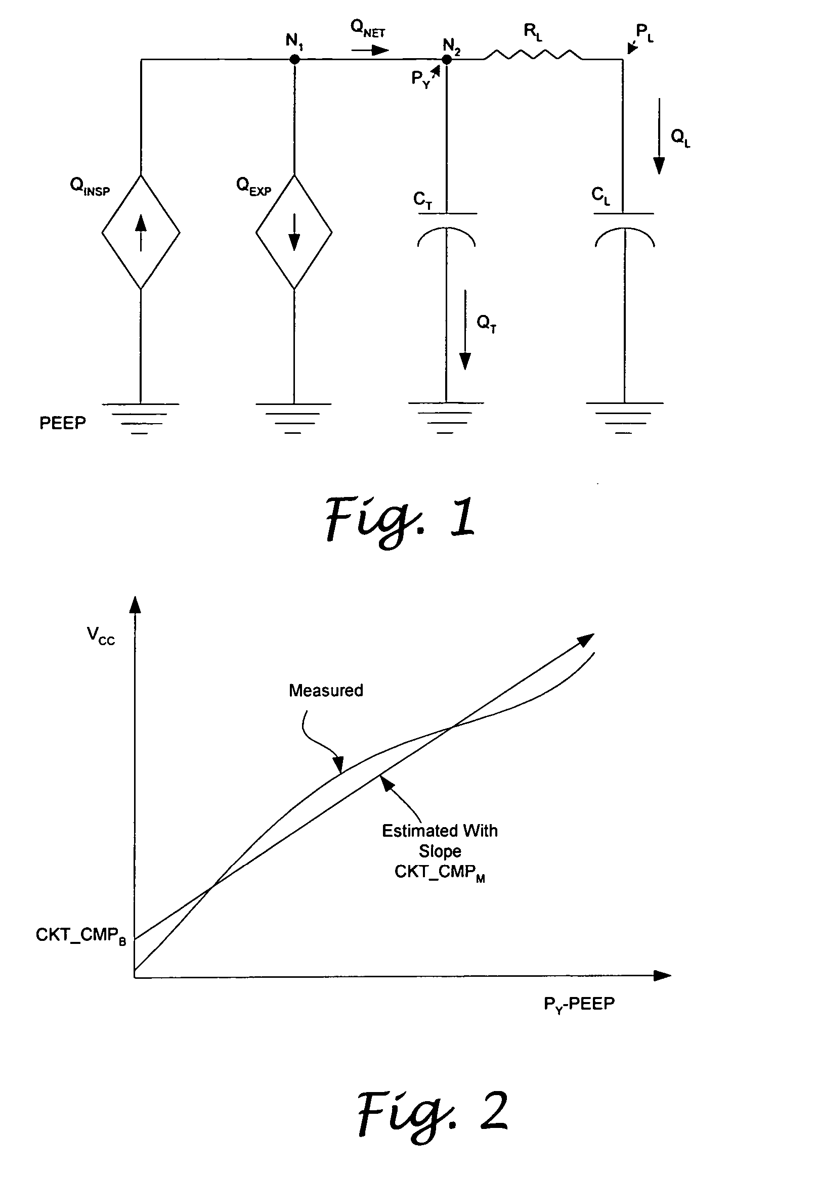
[0018] In an electric circuit, the electric current I flows from a high potential level to a low potential level. When the electric current flows through a passive circuit element such as a resistor, an inductor, a capacitor, or a load, a voltage drop ΔV is created across such element. When electric circuit comprises two or more of the similar circuit elements connected to each other in parallel, the total electric current is split into two smaller currents distributed flowing through the respective elements. The magnitude of the distributed currents depends on the characteristic values, such as the resistance, the conductance and the capacitance of the elements. In a patient respiratory circuit, the gas flow Q circulates from a high pressure level to a low pressure level in a way similar to the electric current I in the electric circuit; and the gas flow I flowing through an airway resistance causes a pressure drop ΔP similar to the voltage drop ΔV. FIG. 1 illustrates a circuit dia...


PUM


Abstract

A system and a method for circuit compliance compensated pressure control in a patient respiratory ventilation system, having a pressure regulated feedback servo control loop, a pressure-regulated volume controller, and a patient volume observer. The patient volume observer is operative to estimate a patient volume, that is, the volume actually delivered to the patient by accounting for volume deviation or loss caused by patient circuit leakage and valve dynamics. Based on the difference between the estimated patient volume and a set tidal volume, the pressure-regulated volume controller is operative to generate and update a circuit compliance pressure compensation factor. The pressure regulated feedback servo control loop is operative to modulate the peak airway pressure based on the circuit compliance pressure compensation factor, so as to achieve the set tidal volume while maintaining a constant inspiratory time and a constant I:E ratio.

Description

CROSS-REFERENCE TO RELATED APPLICATIONS [0001] Not Applicable STATEMENT RE: FEDERALLY SPONSORED RESEARCH / DEVELOPMENT [0002] Not Applicable BACKGROUND [0003] The present invention relates in general to a system and a method for circuit compliance compensated pressure-regulated volume control in a patient respiratory ventilator, and more particularly, to a system and a method suitable for providing ventilation to patients at all sizes and ages by effectively and accurately estimating and compensating for the patient circuit compliance. [0004] In order to deliver an accurate set tidal volume to a patient in a respiratory ventilation system, the patient circuit compliance has to be compensated. The compensation of patient circuit compliance is especially crucial for neonatal patients whose lung compliance can be as small as about one thirteenth of the circuit compliance. Without compensation for the circuit compliance, inaccurate volume delivery and inadequate flow will be delivered to ...

Claims


Application Information

Patent Timeline
IPC IPC(8): A61M16/00
CPCA61M16/0051A61M2016/0021A61M2016/0039A61M2016/0042A61M2205/3344A61M16/026
Inventor SOLIMAN, IHAB S.DUQUETTE, STEVEN
Owner VYAIRE MEDICAL 211 INC
Why Eureka
Try Eureka