Yellow phosphor and white light emitting device incorporating the same
- Summary
- Abstract
- Description
- Claims
- Application Information
AI Technical Summary
Benefits of technology
Problems solved by technology
Method used
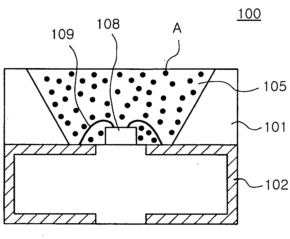
Image

Examples
Embodiment Construction
[0026] The present invention now will be described more fully hereinafter with reference to the accompanying drawings, in which preferred embodiments of the invention are shown. The embodiments described hereunder are only illustrative, and variations and modifications are possible within the scope of the invention.
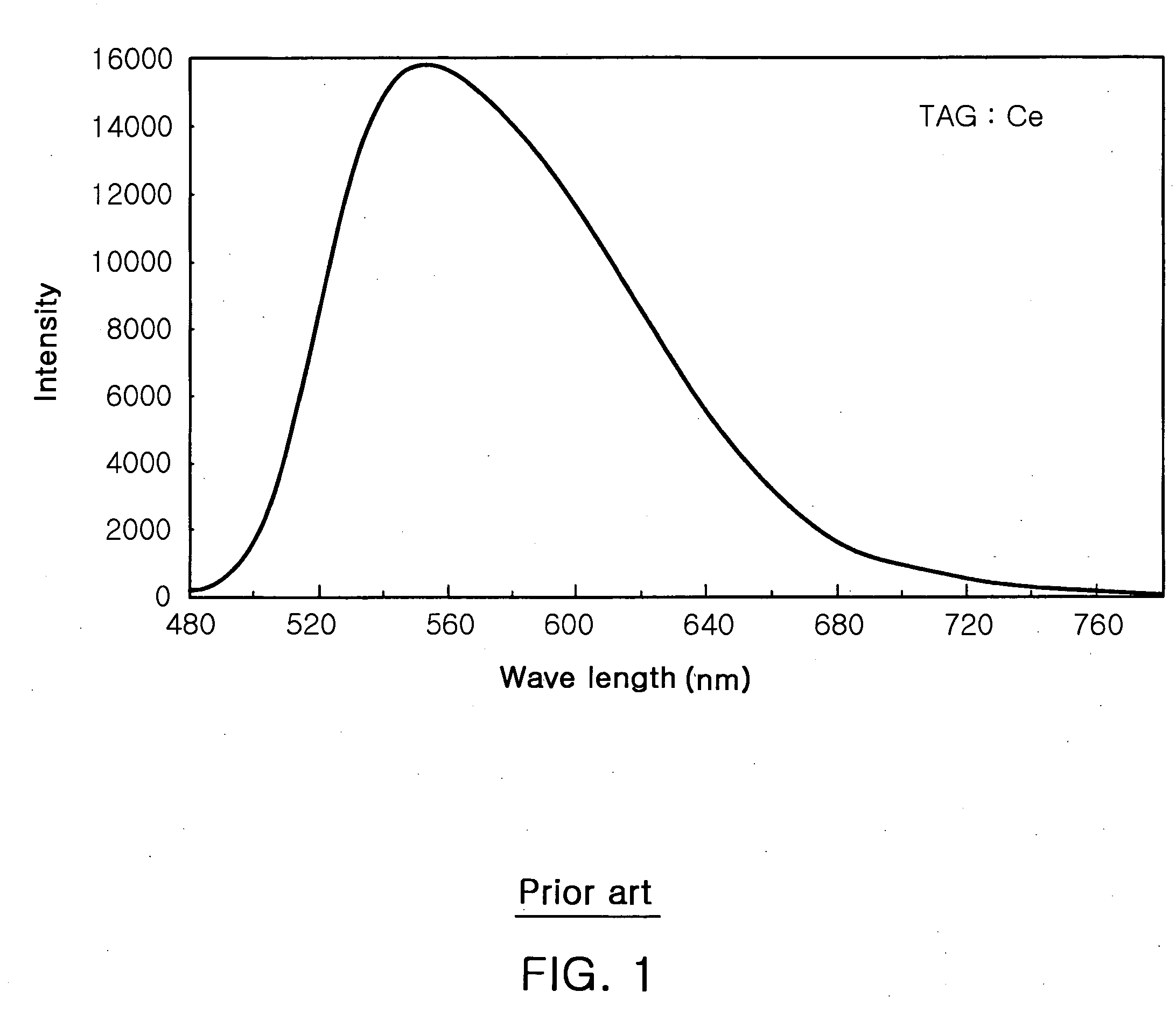
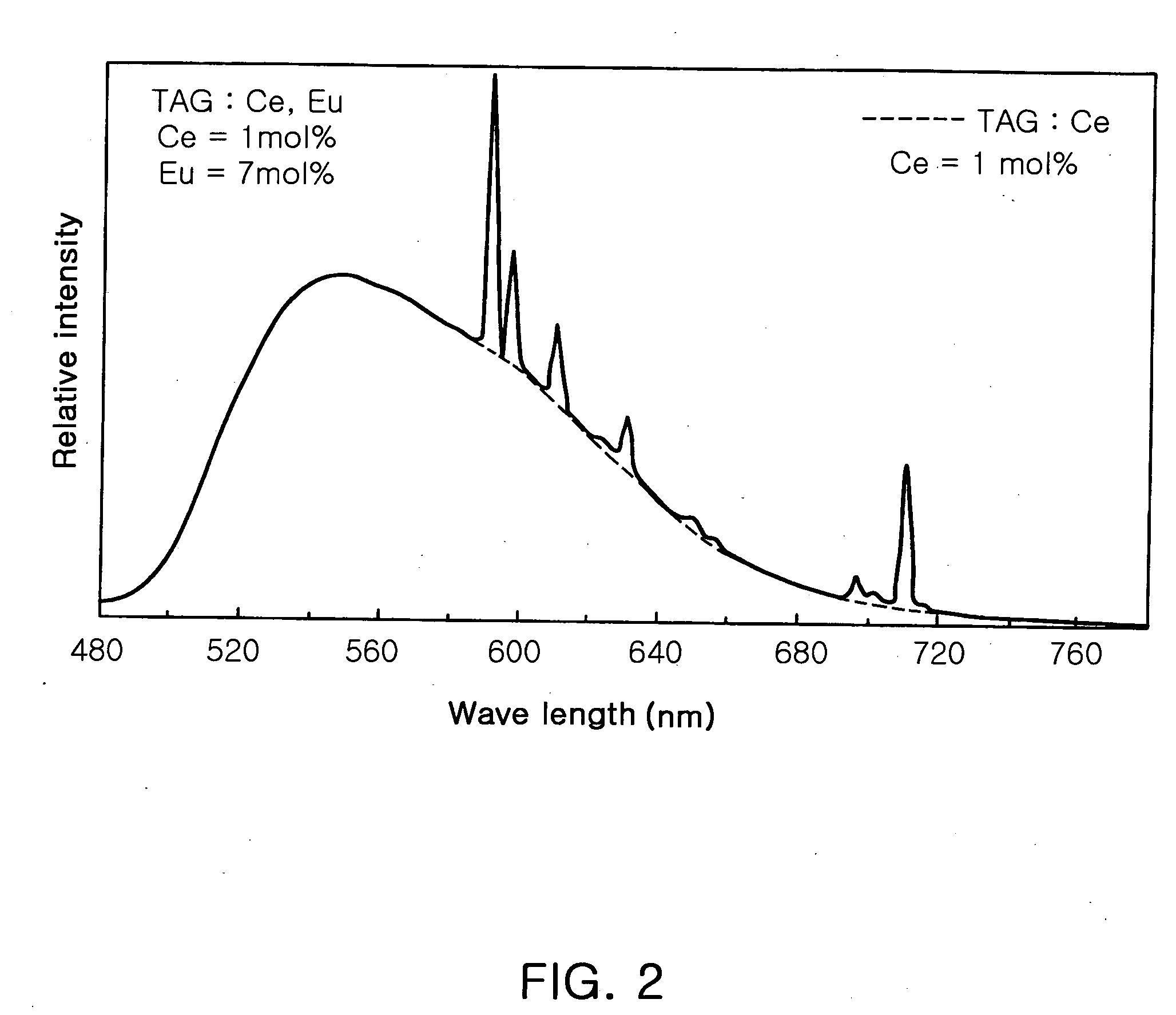
[0027] FIGS. 2 to 5 show the light emission spectra of TAG:Ce,Eu phosphors containing 1 mol % of Ce activator. In particular, to confirm its applicability to a blue LED, the light emission spectra of the phosphors are obtained using excitation light of 460 nm.
[0028] First, FIG. 2 shows the light emission spectrum of TAG:Ce,Eu phosphor containing 7 mol % of Eu co-activator. Referring to FIG. 2, unlike the conventional TAG:Ce phosphor illustrated in FIG. 1, light emission peaks are formed in the red wavelength region due to the Eu co-activator. That is, the light emission spectrum in FIG. 2 (the spectrum of TAG:Ce,Eu) has a form in which the Eu light emission peaks are ad...
PUM
 Abstract
Description
Claims
Application Information
 - R&D
- Intellectual Property
- Life Sciences
- Materials
- Tech Scout
- Unparalleled Data Quality
- Higher Quality Content
- 60% Fewer Hallucinations
Browse by: Latest US Patents, China's latest patents, Technical Efficacy Thesaurus, Application Domain, Technology Topic, Popular Technical Reports.
© 2025 PatSnap. All rights reserved.Legal|Privacy policy|Modern Slavery Act Transparency Statement|Sitemap|About US| Contact US: help@patsnap.com