
Depth image-based rendering method, medium, and system using splats

Active Publication Date: 2007-05-10
SAMSUNG ELECTRONICS CO LTD +1
View PDF7 Cites 59 Cited by
  • Summary
  • Abstract
  • Description
  • Claims
  • Application Information

AI Technical Summary

Benefits of technology

[0027] An embodiment of the present invention provides a depth image-based rendering method, medium, and system that improves a blending speed using only one path.
[0029] A depth image-based rendering method, medium, and system may implement just one path through sequentially blending only splats disposed within a certain distance from surfaces of image data based on an offset value, thereby improving blending speed and the quality of the resultant image.

Problems solved by technology

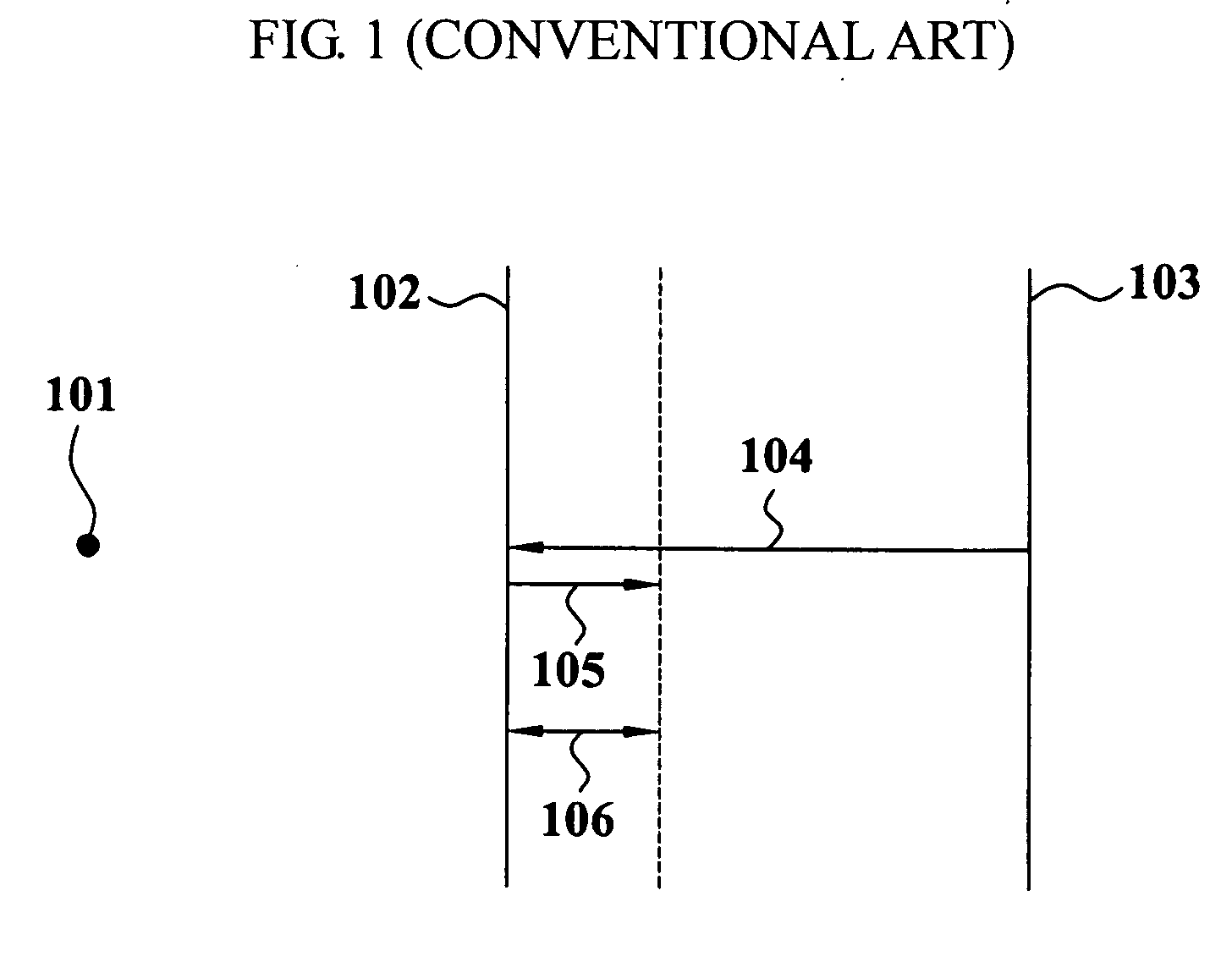
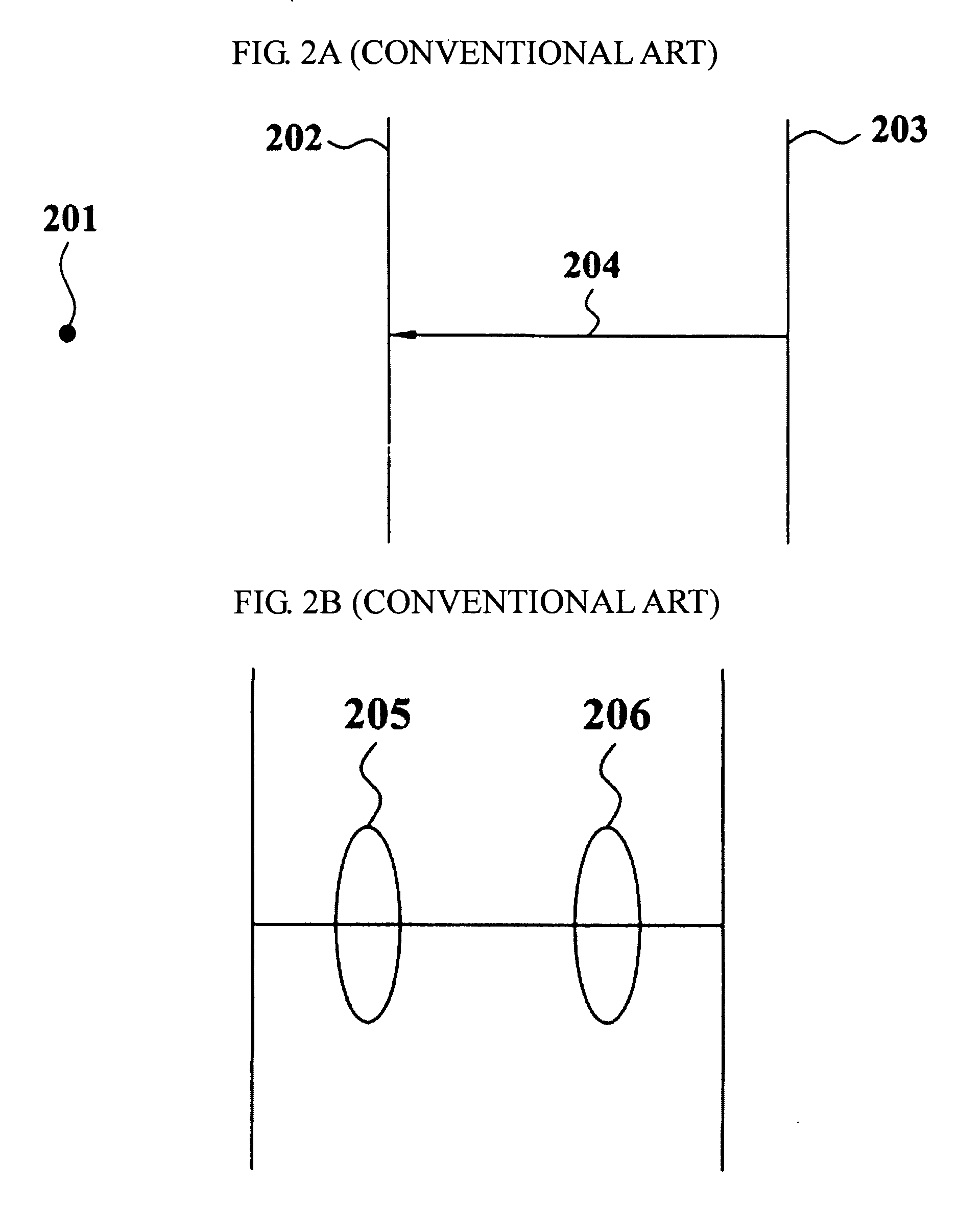
However, there is a disadvantage in that the blending speed is very slow because two paths are required, i.e., first depth information values are calculated from the illustrated 103 surface to an innermost surface along path 104 and the blending is the performed along path 105.
In particular, blending speeds become even slower as image resolutions increase.
However, since information on the closest surface is acquired last, an offset designating a distance from the surface closest to the viewpoint cannot be determined before blending splat, thereby causing image degradation or mixing of image information with background or hidden parts of the image.

Method used


Image

  • Depth image-based rendering method, medium, and system using splats
  • Depth image-based rendering method, medium, and system using splats
  • Depth image-based rendering method, medium, and system using splats

Examples


Embodiment Construction

[0054] Reference will now be made in detail to embodiments of the present invention, examples of which are illustrated in the accompanying drawings, wherein like reference numerals refer to the like elements throughout. Embodiments are described below to explain the present invention by referring to the figures.

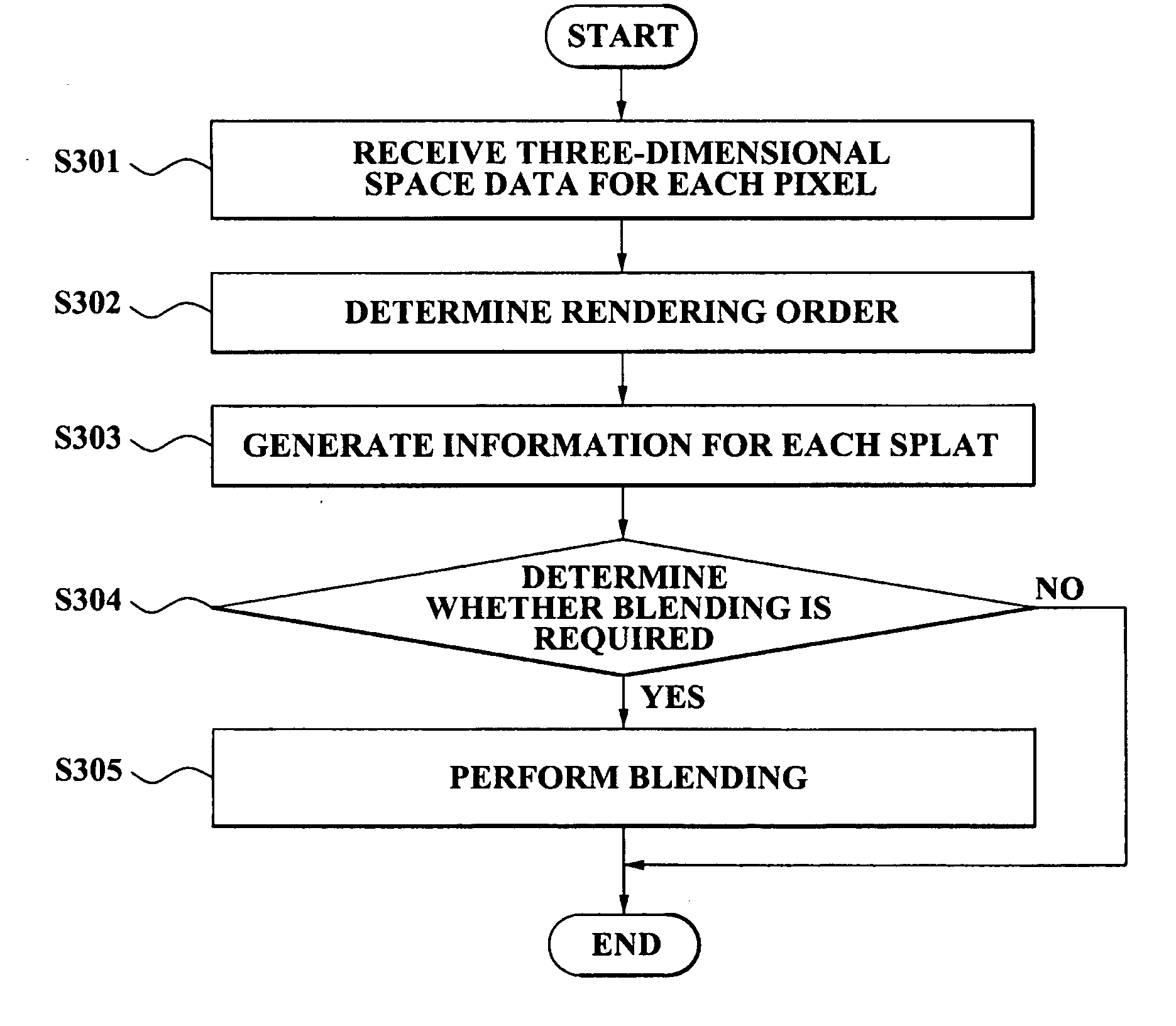
[0055]FIG. 3 illustrates a process of performing depth image-based image rendering for an original image, according to an embodiment of the present invention.

[0056] As shown in FIG. 3, in operation S301, three-dimensional space data may be received for each pixel forming image data, i.e., the three-dimensional space data may include depth information values and color information values for a plurality of pixel.

[0057] The depth information value represents depth information for a pixel in the image data and may be information for evaluating a depth from a surface for the original image data. The color information value may further represent color information for a pixel and...


PUM


Abstract

A method, medium, and system of rendering image data, including receiving three-dimensional space data for each pixel forming the image data, the three-dimensional space data including depth and color information values for each pixel, determining an order of rendering for a plurality of surfaces forming the image data in an order of the distance between a rendering viewpoint and the surface forming the image data, generating splat depth information values for each splat included in the surface forming the image data, according to the rendering order, and determining whether the splat included in the surface forming the image data is required to be blended and accordingly selectively performing a blending on the splat.

Description

CROSS-REFERENCE TO RELATED APPLICATIONS [0001] This application claims the benefit of Korean Patent Application No. 10-2005-107206, filed on Nov. 9, 2005, in the Korean Intellectual Property Office, the disclosure of which is incorporated herein in its entity by reference. BACKGROUND OF THE INVENTION [0002] 1. Field of the Invention [0003] An embodiment of present invention relates to a depth-based image rendering method, medium, and system, and more particularly, to an image-based rendering method, medium, and system that blends splats disposed within a certain offset value from a three-dimensional surface of depth-based image data with one path. [0004] 2. Description of the Related Art [0005] Image-based rendering generates a resultant image from a random viewpoint based on three-dimensional space data of an original certain standard viewpoint (or camera). In such image-based rendering, since a real image can be input, a derivable resultant image may be generated that looks like t...

Claims


Application Information

Patent Timeline
IPC IPC(8): G09G5/00G06T15/20
CPCG06T15/205G06T15/10
Inventor KIM, KEUN HOJANG, GYEONG JALEE, SHIN JUNJUNG, SEOK YOONSUH, MO YOUNGCHUNG, WOO NAMHAN, TACK DON
Owner SAMSUNG ELECTRONICS CO LTD
Learn More