Interior pressure self-adjustable ink supply cartridge structure

a self-adjusting, ink supply technology, applied in printing and other directions, can solve the problems of ink leftover, difficult to have a rear pressure adjustment device precisely and accurately, and inability to take in sufficient amount of ink, etc., to avoid damage caused by wrong operation, and avoid damage

Inactive Publication Date: 2007-05-10
ULIX INT
View PDF5 Cites 26 Cited by
  • Summary
  • Abstract
  • Description
  • Claims
  • Application Information

AI Technical Summary

Benefits of technology

[0006] It is, therefore, the primary purpose of the present invention to provide an interior pressure self-adjustable ink supply cartridge structure wherein, when the ink supply cartridge is put upside down or laid flat in the process of delivery thereof and cause the ink stored therein to abnormally flow backwards, a set of first and second guide channels, a regulation duct, a third guide channel, and a preset empty chamber will sequentially form a buffer space, and the narrowed and winding bends of the regulation duct can prevent air from getting there-through to interact with the refluxed ink thereof so that the ink is simply allowed to retrace at the regulation duct therein, precisely avoiding the problem of ink leakage due to the refluxed ink in the process of application as well as delivery of the ink supply cartridge thereof.
[0007] It is, therefore, the second purpose of the present invention to provide an interior pressure self-adjustable ink supply cartridge structure wherein, in case of the reflux of the ink, the winding bends of the regulation duct can accurately prevent air from getting there-through and producing an interflow effect with the refluxed ink so as to avoid the problem of ink leakage thereby. And due to the narrowed and winding regulation duct to effectively prevent the ink from leaking outside the cartridge thereof, no other leak-proof sticky paper is required to be applied to an air vent of the ink supply cartridge or released there-from so as to avoid the damage caused by wrong operation thereof. Besides, the ink supply cartridge can be directly refilled with ink via a set of first and second ink refilling ports without being removed from a printer for the purpose thereof, economically facilitating an easy and fast application thereof.
[0008] It is, therefore, the third purpose of the present invention to provide an interior pressure self-adjustable ink supply cartridge structure wherein a first linkage shallow channel is provided to connect an ink accommodating chamber and a first ink reservoir of the ink supply cartridge so that, during the refilling process of the ink accommodating chamber and the first ink reservoir thereof, air taken inside the cartridge can be drained there-from via a second linkage shallow channel connected to the upper edge of the first ink reservoir and, thus, when the ink is being refilled via the second ink refilling port thereof, the refilled ink will not be brought outwards along with the refluxed air and cause untidy ink stains at the ink supply cartridge thereon. Besides, the ink supply cartridge can be directly refilled with ink via the first and second ink refilling ports without being removed from the printer thereof, achieving more convenient application thereof.
[0009] It is, therefore, the fourth purpose of the present invention to provide an interior pressure self-adjustable ink supply cartridge structure wherein the ink accommodating chamber of the ink supply cartridge is designed according to the volume of the ink container thereof and proportioned by the principles of relative density and space thereof so that when the ink accommodating chamber is refilled to the full and located onto a printer, the refilled ink will not leak out through an ink outlet port communicated with the ink accommodating chamber thereof.
[0010] It is, therefore, the fifth purpose of the present invention to provide an interior pressure self-adjustable ink supply cartridge structure wherein, when the ink supply cartridge is installed onto a printer for ink supply thereof, the second linkage shallow channel will form an air interflow channel inside the ink supply cartridge thereof, permitting outside air to enter the preset empty chamber through the air vent and travel in a series through the third guide channel, the regulation duct, the second guide channel, the second ink reservoir, and the first guide channel to go through a passageway and enter the first ink reservoir via the second linkage shallow channel thereof. When the air enters the second ink reservoir, the intake air will interact with the ink-pulling operation of the printer to produce a pull-and-push effect therewith, permitting the air inside the ink supply cartridge to be appropriately buffered and automatically regulated in pressure so as to maintain the negative pressure established at the ink supply cartridge therein on a certain level, efficiently avoiding the problem of ink leakage or the situation of abnormal ink supply thereof.

Problems solved by technology

However, with the porous material accommodated therein and to avoid the problem of ink leakage, the first conventional ink supply cartridge usually cannot take sufficient amount of ink therein.
And, when the filled ink is consumed in part, the porous material without any ink stayed therein will take in outside air inside the ink supply cartridge, which can interfere with the regular supply of the filled ink and cause the problem of ink leftover.
Besides, most of the porous material is made of foaming material and fibers, both of which, over long time of use, tend to produce tiny particles like short fibers to block the ink outlet port and get in the way of regular ink supply for use thereof.
However, it is really difficult to have a rear pressure adjustment device precisely and accurately made.
First of all, the inner parts of the adjustment device thereof must be delicately processed, which, in terms of today's technology, is still to be improved and can boost the cost of production thereof.
Besides, the rear pressure adjustment device thereof must be accurately mounted to the ink supply cartridge, which is quite complex in the process and can also increase the cost of processing thereof.
However, the third conventional ink supply cartridge has several disadvantages.
As a result, the continuous reduction of the filled ink will cause the negative pressure inside the ink cartridge to pass over the allowed limitation and make the ink droplets difficult to jet outwards.
Therefore, the leftover ink will stay in the ink supply cartridge and uneconomically become a waste of the ink in application thereof.
In case the sticky paper is not appropriately removed from the ink cartridge before application thereof, the air inside the ink cartridge will not interact with the ink and provide proper ink supply for use of the printer, which can easily damage the printer as well as the ink cartridge thereof.
Besides, when the conventional ink supply cartridge is refilled with ink, the air inside the ink cartridge thereof must be drained outwards via ink refilling ports, which can bring out the refilled ink therewith and stain the ink refilling ports with ink marks.
Thus, the conventional ink supply cartridge is quite inconvenient in application.
Finally, the ink accommodating chambers of the conventional ink supply cartridges thereof are not appropriately designed according to the principles of relative density and space thereof, which can cause the problem of bad ink leakage when the ink supply cartridges are filled with ink to the full and installed onto printers for use thereof.

Method used


Image

  • Interior pressure self-adjustable ink supply cartridge structure
  • Interior pressure self-adjustable ink supply cartridge structure
  • Interior pressure self-adjustable ink supply cartridge structure

Examples


Embodiment Construction

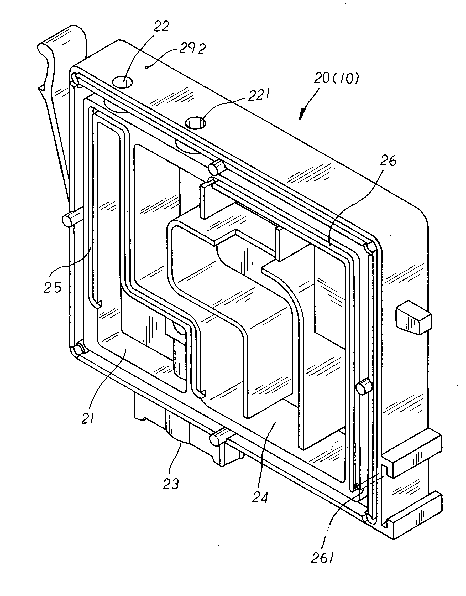
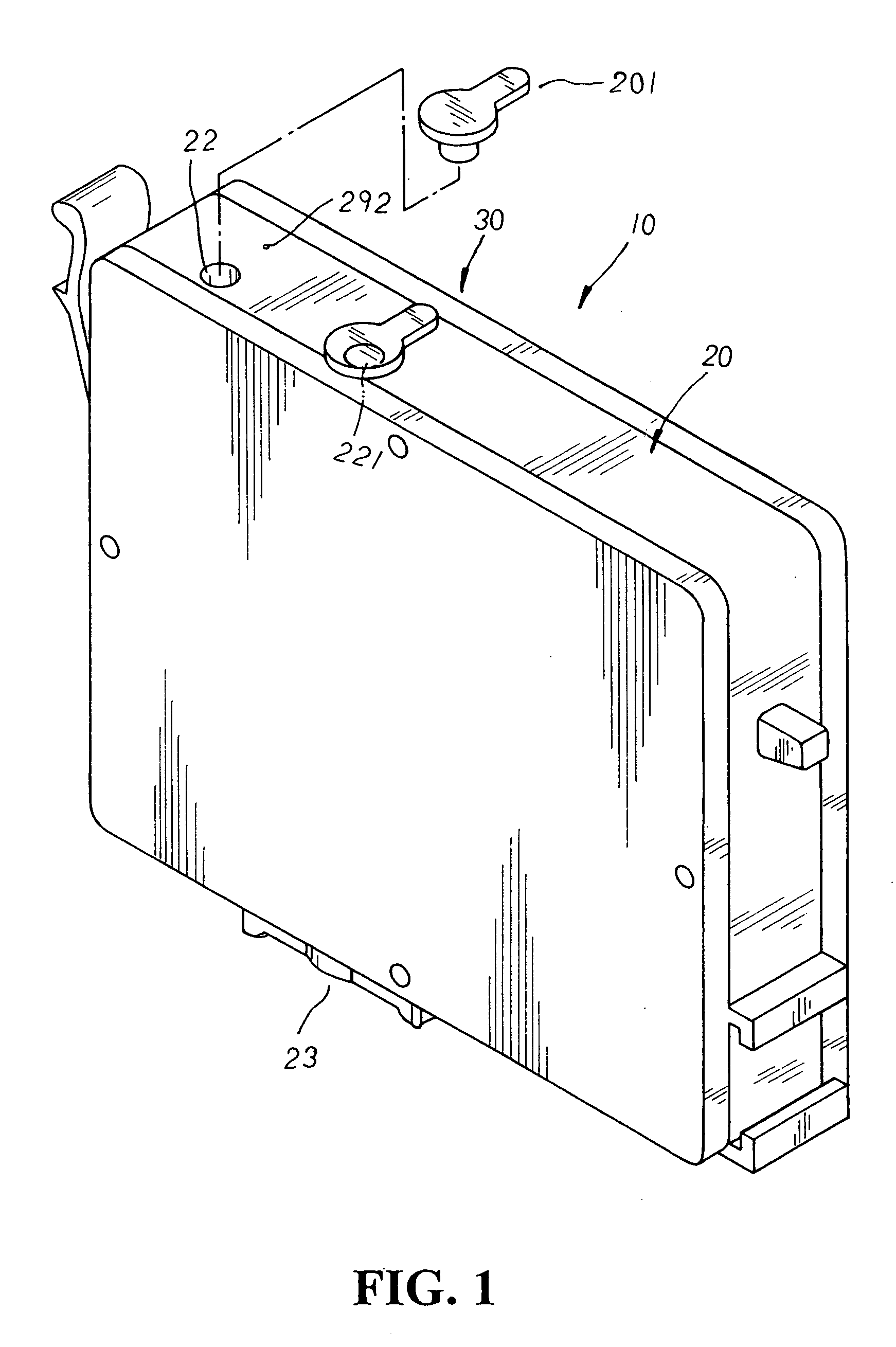
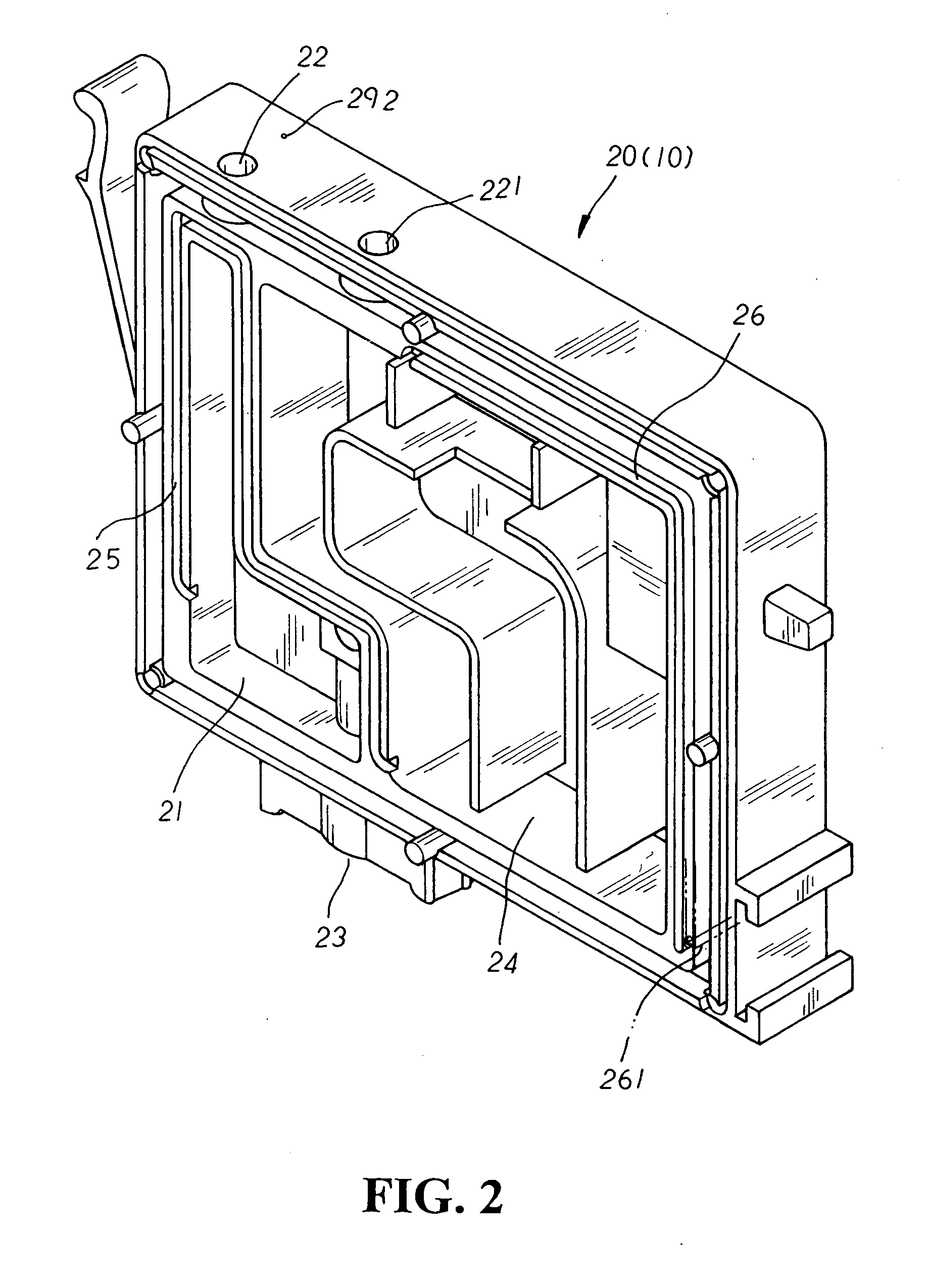
[0016] Please refer to FIG. 1 showing a perspective view of the present invention (accompanied by FIG. 2 showing an interior perspective view of one lateral side of the present invention). The present invention is related to an interior pressure self-adjustable ink supply cartridge structure, comprising an ink supply cartridge 10 made up of an ink container 20, and a thermal film 30 sealed off at one outer side of the ink container 20 wherein the ink container 20 has an ink accommodating chamber 21 of a proper depth appropriately indented one inner lateral side thereof and proportioned according to the principles of relative density and space thereof for the accommodation of ink therein. At the top and bottom sides of the ink container 20 is respectively disposed a first ink refilling port 22 and an ink outlet port 23 correspondingly communicated with the ink accommodating chamber 21 thereby wherein the ink outlet port 23 thereof is reciprocally associated with a non-illustrated ink...


PUM


Abstract

An interior pressure self-adjustable ink supply cartridge structure comprises an ink container having an ink accommodating chamber and an adjacent first ink reservoir disposed at one inner side therein wherein a first linkage shallow channel is provided to connect the ink accommodating chamber and the first ink reservoir thereby, and a second linkage shallow channel is associated with the upper edge of the first ink reservoir thereof. A passageway is linked to the other end of the second linkage shallow channel and passed across to a first guide channel of a second ink reservoir disposed at the other inner side of the ink container therein. A second guide channel is disposed extending at the other side of the second ink reservoir to communicate with a continuous winding and shallow regulation duct to which a third guide channel is connected at the other end thereof to associate the regulation duct with a preset empty chamber having an air vent disposed at the upper edge thereon. Via the aforementioned structure thereof, no matter in what state the ink supply cartridge is, whether it's being delivered, opened for ink supply, or shutoff from ink supply thereof, the negative pressure established at the ink accommodating chamber therein can be appropriately maintained on a certain level, efficiently achieving an automatic self-adjustment of interior pressure of the ink supply cartridge so as to avoid the problem of ink leakage or the situation of abnormal ink supply thereby.

Description

BACKGROUND OF THE INVENTION [0001] The present invention is related to an interior pressure self-adjustable ink supply cartridge structure, including an ink container having an ink accommodating chamber and an adjacent first ink reservoir disposed at one inner side therein wherein the ink accommodating chamber is connected to an ink outlet port to provide ink supply for use of a printer thereby, and when the ink stored therein is depleted, the ink container can be directly refilled via a set of first and second ink refilling ports to economically facilitate the reapplication of the ink supply cartridge thereby. Besides, via a regulation duct whose winding bends thereof can effectively prevent air from interacting with refluxed ink so as to avoid the problem of ink leakage and to omit any sticky paper applied onto an air vent for leak-proof purpose thereof. [0002] There are basically three conventional types of ink supply cartridges for use of ink jet printers. First, there is an ink...

Claims


Application Information

Patent Timeline
Patent Type & Authority Applications(United States)
IPC IPC(8): B41J2/175
CPCB41J2/17513B41J2/17553B41J2/17556
Inventor WU, GWO JYH
Owner ULIX INT
Why Eureka
Try Eureka