Sectional light emitting diode backlight unit

a technology of light-emitting diodes and backlight units, which is applied in the field of sectional led backlight units, can solve the problems of inability to match the flat display panels having different sizes, large thickness, and non-uniform luminance, and achieves the effects of convenient replacement, reduced thickness, and simple package process

Inactive Publication Date: 2007-05-10
LIGHTHOUSE TECH
View PDF14 Cites 59 Cited by
  • Summary
  • Abstract
  • Description
  • Claims
  • Application Information

AI Technical Summary

Benefits of technology

[0010] The sectional light emitting diode backlight unit according to the present invention can be combined as a large-sized backlight unit for a large-sized display panel such as LCD TV. Therefore, the present invention has the advantages as follows. The backlight unit can be manufactured in a relatively smaller size with a simpler package process, and combined as a direct light backlight unit with proper size when applied to a large-sized flat display panel. Since the circuit of each backlight unit is independent, it is convenient to replace it when failed. A plurality of light emitting diode dies are directly disposed on the circuit board so that the resulting backlight unit thickness is thinner than using a plurality of mono-chip light emitting diode packages disposed on the circuit board. A desired luminance of the backlight unit can be maintained by a local adjustment in accordance with the decrease of light intensity sensed by a light sensor.

Problems solved by technology

However, for a better optical performance, this conventional LED backlight unit will have the disadvantages of larger thickness and non-uniform luminance.
This kind of LED backlight unit has a fixed size when being assembled, and thus it is not able to match the flat display panels having different sizes.

Method used


Image

  • Sectional light emitting diode backlight unit
  • Sectional light emitting diode backlight unit
  • Sectional light emitting diode backlight unit

Examples


Embodiment Construction

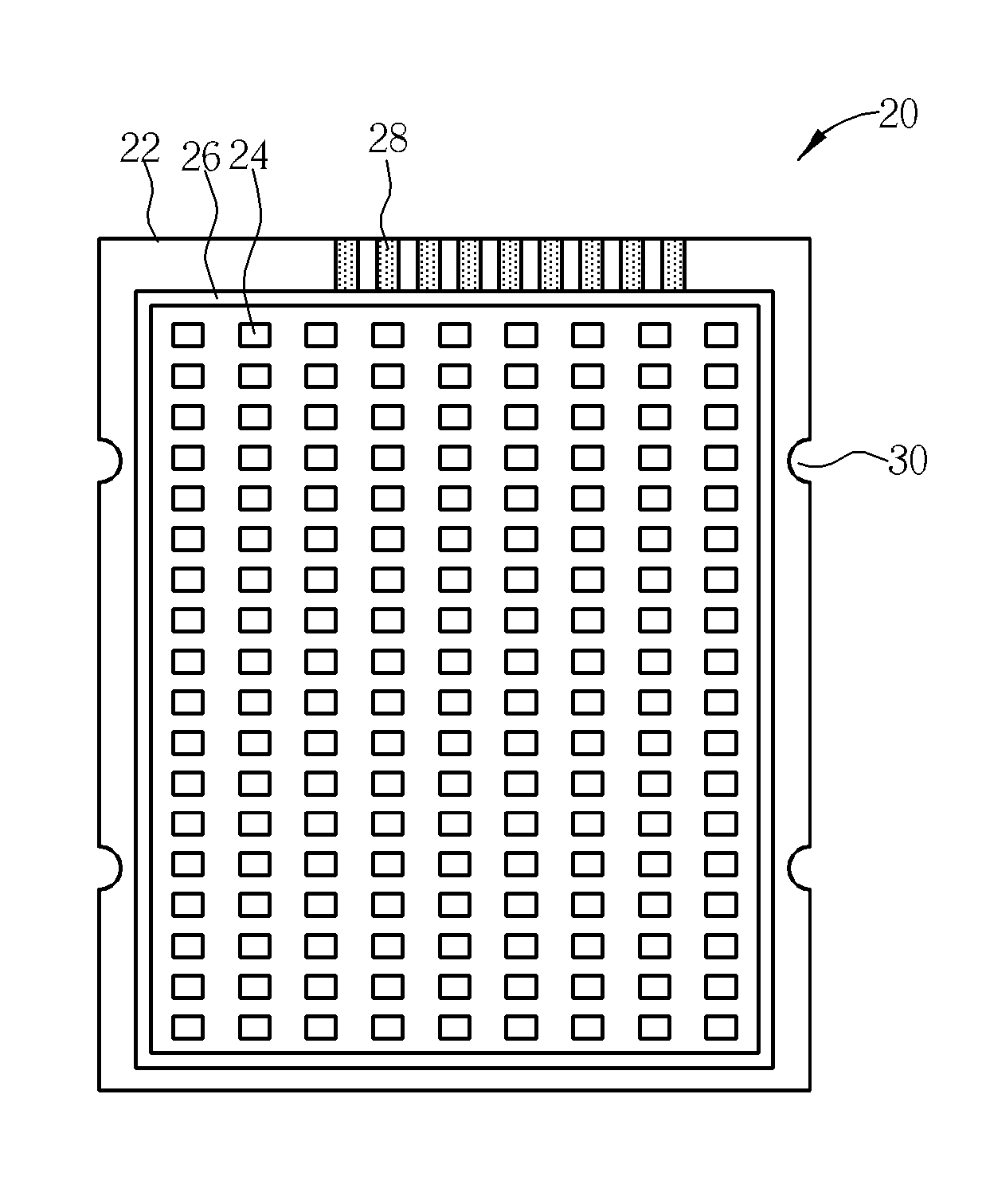
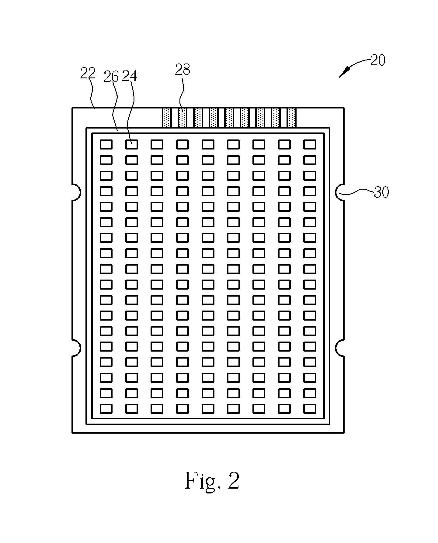
[0019] Please refer to FIG. 2 and FIG. 3. FIG. 2 shows an embodiment of the sectional LED backlight unit according to the present invention, and FIG. 3 is a schematic cross-sectional view of the sectional LED backlight unit shown in FIG. 2. The sectional LED backlight unit 20 comprises a circuit board 22, a plurality of LED dies 24, a frame 26, a plurality of connecting pads 28, and an encapsulating material 32, wherein the circuit board 22 has one or more connection means 30 for assembly with one or more another sectional LED backlight units to form a larger backlight device.

[0020] The circuit board 22 has a circuit to electrically connect the LED dies or other components positioned on the circuit board with a control device or power supply device. Since the high power LED backlight unit produces relatively more heat, materials with better heat conduction are preferred to be the circuit board. The circuit can be designed as a single layer or multi-layer as desired. It is preferred...


PUM


Abstract

A sectional light emitting diode backlight unit comprising a circuit board, a frame disposed on the circuit board, a plurality of light emitting diode dies disposed on the circuit board inside the frame, each light emitting diode die being electrically connected to a circuit on the circuit board, a plurality of connecting pads disposed on a first side of the circuit board outside the frame, the connecting pads being electrically connected to a circuit on the circuit board, and an encapsulating material positioned on the circuit board inside the frame to cover the light emitting diode dies; wherein at least one second side of the circuit board has a connection means for connecting to another sectional light emitting diode backlight unit.

Description

BACKGROUND OF THE INVENTION [0001] 1. Field of the Invention [0002] The present invention relates to a light emitting diode (LED) backlight unit, and more particularly to a sectional LED backlight unit. [0003] 2. Description of the Prior Art [0004] Most of the light source generators in the traditional liquid crystal display (LCD) backlight units are cold cathode fluorescent lamps (CCFL) nowadays, but since the CCFL consists of mercury (Hg), the CCFL will be possibly superseded under the requirement for green merchandises in the future. The light emitting diode (LED) is being substituted for the CCFL stage by stage as the light source generators in the LCD, LCD TV, or other flat display panels with various sizes. In addition, the light intensity per watt of the LED is gradually becoming higher enough for application in the backlight unit due to the improvement in the LED technology. [0005] In a conventional LED backlight unit, the LED package is positioned directly under the panel, ...

Claims


Application Information

Patent Timeline
Patent Type & Authority Applications(United States)
IPC IPC(8): F21V7/04
CPCG02B6/0068G02B6/0078G02F1/133603G02F1/133608G02F2001/133612G02F1/133612
Inventor HUANG, TENG-HUEIFAN, CHU-PINGLEE, CHIEN-LUNG
Owner LIGHTHOUSE TECH
Why Eureka
Try Eureka