Fixing device for a vacuum pump

a vacuum pump and fixing device technology, applied in the direction of piston pumps, positive displacement liquid engines, liquid fuel engines, etc., can solve the problems of bolt breakage, bolts may break, and the structure may be detached, so as to improve the damping capacity, increase the volume of the studs, and increase the radius of curvature

Inactive Publication Date: 2007-05-10
ALCATEL LUCENT SAS
View PDF41 Cites 15 Cited by
  • Summary
  • Abstract
  • Description
  • Claims
  • Application Information

AI Technical Summary

Benefits of technology

[0028] The housing delimited by the coupling of the cavity on the flange and the cavity at the end of the pump body is advantageously of oblong shape in order to increase the volume of the studs, with the aim of improving their damping capacity, at the same time as complying with the geometrical constraints of the standard.
[0029] In one particular embodiment of the invention, the cavities forming the housing when coupled are of rounded shape with different radii of curvature for each of the cavities. One of the cavities forming the housing preferably has a rounded shape espousing that of the stud and rounded corners in order to prevent contact with sharp edges degrading the stud. The other cavity has a much larger radius of curvature, allowing working in compression, reducing the stress on the stud. In this type of configuration, compression of the studs in the housing allows a 30° rotation of the pump body, preventing the studs from breaking.

Problems solved by technology

On the other hand, it has been found that an insurmountable problem may arise in the event of accidental destruction of the pump rotor when rotating at full speed.
This results in violent shear forces on the fixing bolts, and it has been found that in current structures these forces cause the bolts to break.
The pump is then detached from the structure and constitutes a dangerous projectile that can fly around the place of use.
In the event of a pump crash, the energy that must be dissipated and not transmitted to the structure becomes much greater and in this configuration the yield strength prior to the bolts breaking becomes insufficient.
Furthermore, this solution does not prevent the pump from becoming detached from the structure in the event of the bolts breaking.

Method used


Image

  • Fixing device for a vacuum pump
  • Fixing device for a vacuum pump
  • Fixing device for a vacuum pump

Examples


Embodiment Construction

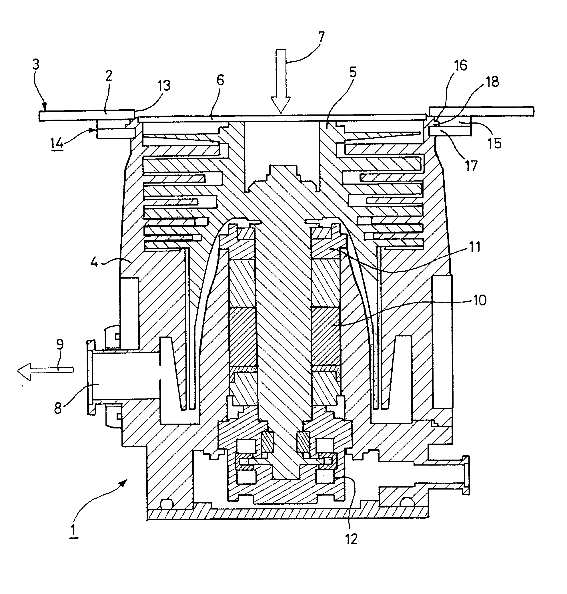
[0048] Consider first of all FIG. 1, showing a turbomolecular type vacuum pump structure 1 fastened to a wall 2 associated with a structure 3 such as a vacuum enclosure, for example.

[0049] The vacuum pump 1 comprises a pump body 4 in which a rotor 5 rotates at high speed about the axis I-I of the pump body 4. The pump body 4 includes an inlet orifice 6 coaxial with the pump body 4 through which the pumped gases 7 enter and a discharge orifice 8 through which the discharge gases 9 are evacuated. The rotor 5 is driven in rotation in the pump body 4 by an internal motor 10 and is guided laterally by magnetic or mechanical bearings 11 and 12.

[0050] The wall 2 associated with the structure 3 comprises a pumped gas outlet orifice 13 in corresponding relationship with the inlet orifice 6 of the vacuum pump 1. The structure 3 delimits a closed enclosure isolated from the outside environment and in which the vacuum pump 1 is able to create a controlled vacuum. The wall 2 may be the envelop...


PUM


Abstract

The present invention relates to the field of high rotation speed vacuum pumps, which are fastened to and connected to a structure such as a vacuum enclosure or a pipe to generate a hard vacuum. It consists in an annular fixing flange including holes cooperating with headed bolts to fasten a vacuum pump to a structure. The flange comprises an upper ring and a lower ring cooperating to clamp the end of the pump body between the upper ring and the lower ring, and at least one first cavity in a face of the upper ring that is in a plane perpendicular to that of the face of the upper ring intended to come into contact with the wall of the structure. The invention also consists in a fixing system comprising an annular flange disposed coaxially with the pump body around the inlet orifice of the pump. At least one second cavity in the face of the end of the pump body in contact with a face of the upper ring is coupled with the first cavity to form a housing, and at least one flexible material stud inserted into the housing.

Description

CROSS-REFERENCE TO RELATED APPLICATIONS [0001] This application is based on French Patent Application No. 0553428 filed Nov. 10, 2005, the disclosure of which is hereby incorporated by reference thereto in its entirety, and the priority of which is hereby claimed under 35 U.S.C. § 119. BACKGROUND OF THE INVENTION [0002] 1. Field of the Invention [0003] The present invention relates to the field of high rotation speed vacuum pumps, which are fastened to and connected to a structure such as a vacuum enclosure or a pipe to generate a hard vacuum. It concerns more particularly a device for fixing such vacuum pumps. [0004] 2. Description of the Prior Art [0005] In the electronic and micromechanical component industries, machining or plasma processing methods are executed inside an enclosure in which a controlled vacuum must be maintained. [0006] Generating the vacuum necessitates the use of pumps capable of quickly generating and maintaining a hard vacuum adapted to the machining or proc...

Claims


Application Information

Patent Timeline
Patent Type & Authority Applications(United States)
IPC IPC(8): F04B17/00
CPCF04D19/042Y10T403/64F04D27/0292F04D29/601F16B2200/50F05D2210/12Y10S417/00
Inventor VARENNES, NICOLASDAUVILLIER, OLIVIER
Owner ALCATEL LUCENT SAS
Why Eureka
Try Eureka