Folding machine with a rotary stand

Active Publication Date: 2007-05-10
MBO POSTPRESS SOLUTIONS GMBH
View PDF6 Cites 1 Cited by
  • Summary
  • Abstract
  • Description
  • Claims
  • Application Information

AI Technical Summary

Benefits of technology

[0006] The invention is based on the object of providing a folding machine which can be adapted rapidly and simply to different types of fold.
[0008] The design of the folding machine according to the invention makes it possible, depending on the desired type of fold, to arrange the three-fold module rapidly and simply on one of the two sides of the cross-fold folding blade. Since the cross-fold folding blade and the sheet-supporting device remain in a fixed position, if appropriate with a holding-down device and an end-stop device being included, it is merely required to rotate the roller frame and the three-fold module about the vertical axis of rotation.
[0009] The flexibility of the folding machine is further increased if on the rotary stand a folding buckle device is arranged, with respect to the axis of rotation, diametrically opposite the three-fold module. This creates the possibility of folding a sheet, which has been folded by the cross-fold folding blade, on both sides of the cross-fold folding blade both by means of a folding buckle device and by means of a three-fold module.
[0010] The rotation of the rotary stand is simplified if the cross-fold folding blade and the sheet-supporting device of the cross fold module are fitted on a frame which is mounted in a manner such that it can be pivoted upwards about a pivot axis. If the frame is pivoted upwards, the rotary stand together with the roller frame, the three-fold module and, if appropriate, the folding buckle device can be rotated freely about the axis of rotation.

Problems solved by technology

However, the conveying device which can be switched over is very complicated in terms of structure.
In addition, the adaptation of the moveable second basic module to the first basic module is difficult, since the position has to be precisely positioned.

Method used


Image

  • Folding machine with a rotary stand
  • Folding machine with a rotary stand
  • Folding machine with a rotary stand

Examples


Embodiment Construction

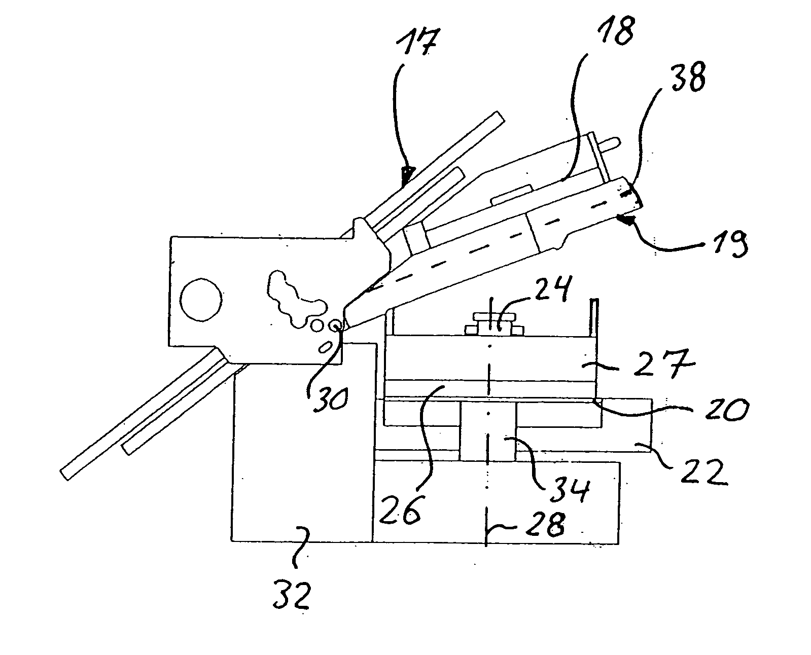
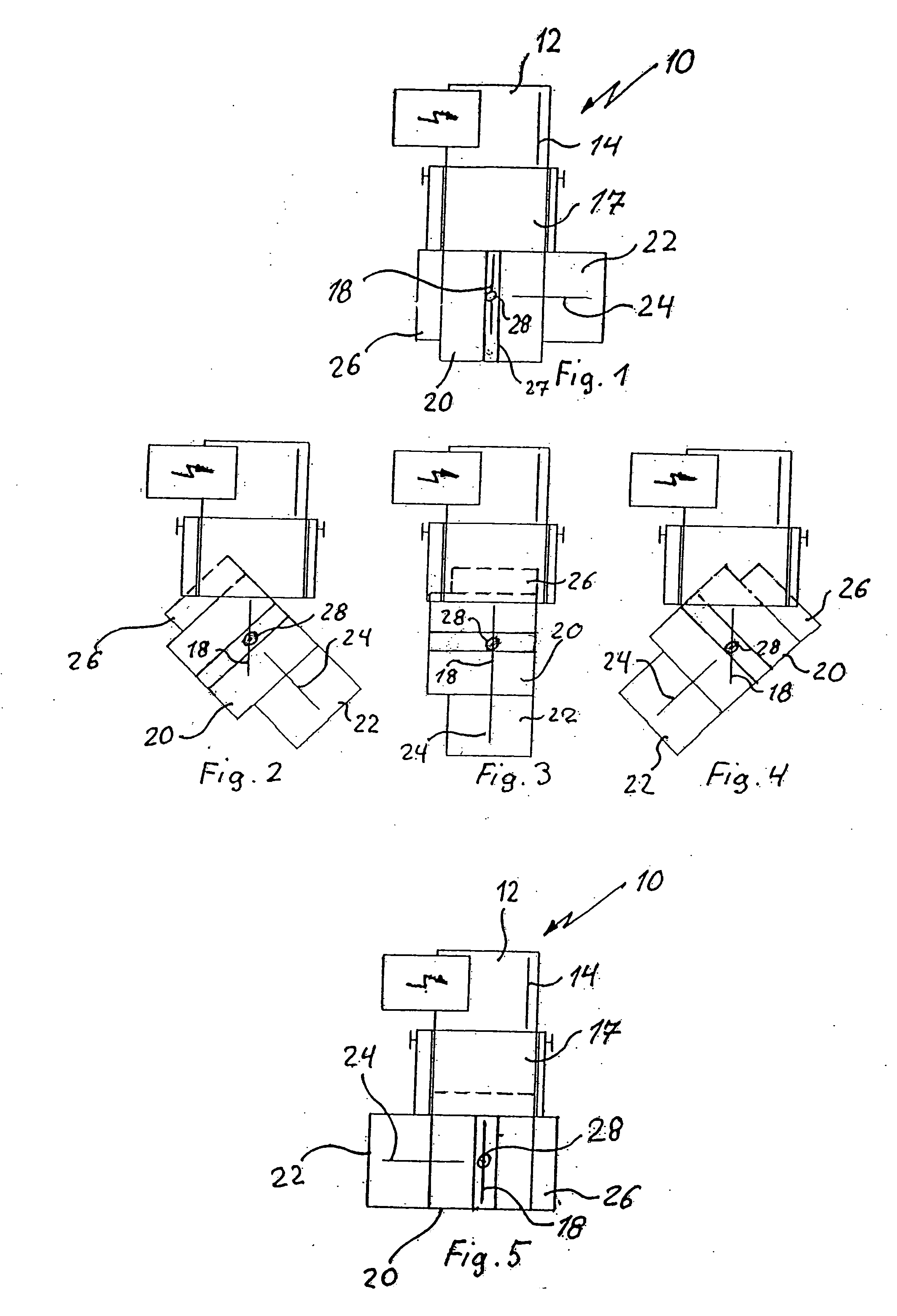
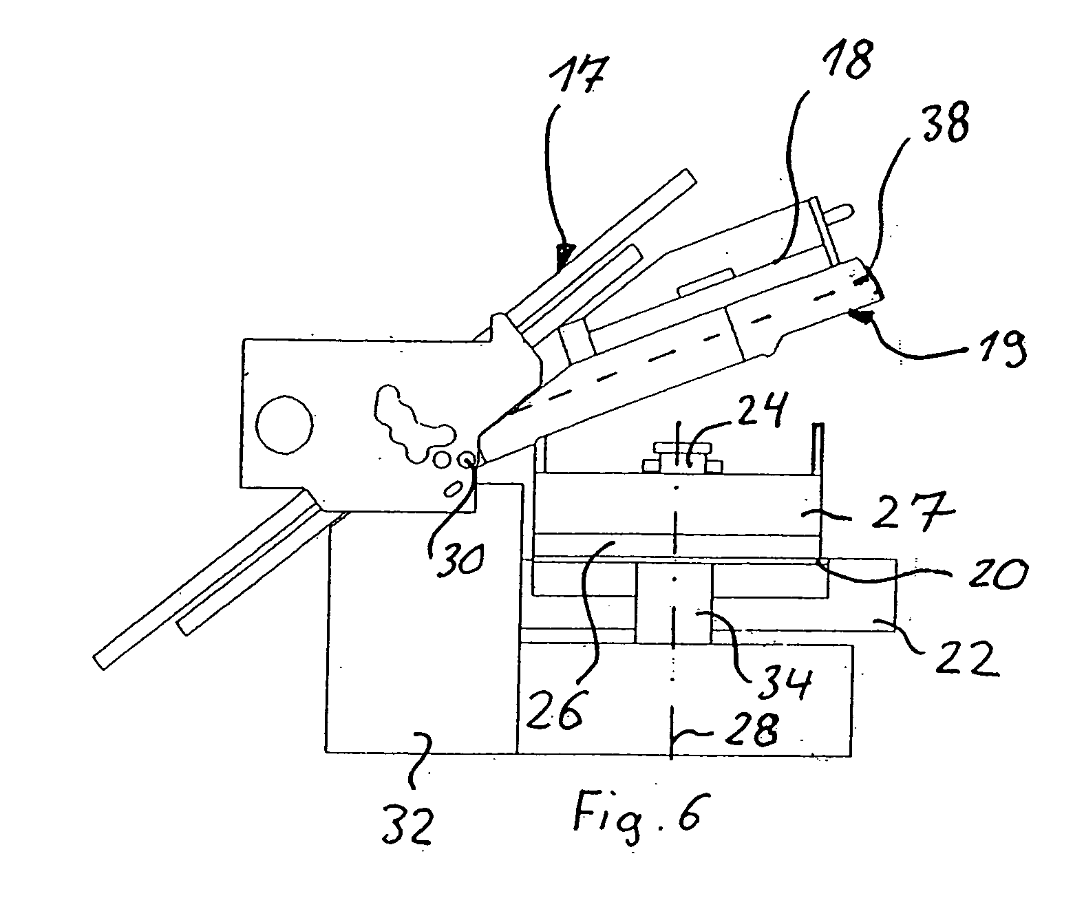
[0018] The folding machine shown in FIGS. 1 to 6 comprises an aligning table 12 with a sloping conveying belt and a stop strap 14 which extends in the sheet running direction by means of which a sheet conveyed by the sloping conveyor belt is aligned in the sheet running direction before it is introduced into a buckle folding device 17 which is arranged downstream of the aligning table 12. Arranged downstream of the buckle folding device 17 in the sheet running direction is a cross fold module 19 which comprises a cross-fold folding blade 18 which is arranged above a sheet-supporting device 38 (FIG. 6) which is preferably formed by a plurality of endless transporting belts arranged in parallel at a distance from one another. In addition, the cross fold module can have a holding-down device for holding down an incoming sheet and an end stop device against which an incoming sheet comes to bear with its leading edge.

[0019] As can be seen in FIG. 6, the cross-fold folding blade 18 and th...


PUM

PropertyMeasurementUnit
Angleaaaaaaaaaa

Abstract

The folding machine has a cross fold module which includes a cross-fold folding blade (18), a sheet-supporting device (38) which is arranged below the cross-fold folding blade (18) and on which an incoming sheet comes to rest, and a roller frame (27) which is arranged below the sheet-supporting device (38) and into which a sheet is introduced by the cross-fold folding blade (18). A three-fold module (22) with a three-fold folding blade (24) arranged perpendicularly with respect to the cross-fold folding blade (18) is arranged downstream of the roller frame (27). The three-fold module (22) and the roller frame (27) are arranged on a rotary stand (20) which is rotatable through at least 180° about a vertical axis (28).

Description

BACKGROUND OF THE INVENTION [0001] 1. Field of the Invention [0002] The invention relates to a folding machine comprising a cross-fold module having a cross-fold folding blade, a sheet-supporting device which is arranged below the cross-fold folding blade and on which an incoming sheet comes to rest, and a roller frame which is arranged below the sheet-supporting device and into which a sheet is introduced by the cross-fold folding blade, and a three-fold module which is arranged downstream of the roller frame and has a three-fold folding blade arranged perpendicularly with respect to the cross-fold folding blade. [0003] 2. Description of the Background Art [0004] DE 31 47 064 A1 discloses a folding-device assembly which has a first basic module which has, successively in the sheet-running direction, a supply table for supplying sheets and a buckle folding device. Arranged downstream of the first basic module is a second basic module which comprises a cross fold module on the one si...

Claims


Application Information

Patent Timeline
IPC IPC(8): B31F1/00
CPCB65H45/12B65H45/18B65H2404/66B65H45/14B65H45/142B65H2220/09B65H2402/35
Inventor BECK, CHRISTOPHDANNEMANN, GEORGSAILER, MARTINKRIEGER, EBERHARD
Owner MBO POSTPRESS SOLUTIONS GMBH
Why Eureka
Try Eureka