
Lumen traversing device

a technology of lumen walls and traversing devices, which is applied in the field of lumen traversing devices, can solve the problems of increasing difficulty in pushing a flexible scope around bends in the gi tract, affecting the accuracy of gi tract bending, and many conventional endoscopes have an inherent problem of access, so as to facilitate gripping of the lumen walls and reduce slippag

Active Publication Date: 2007-05-10
ETHICON ENDO SURGERY INC
View PDF99 Cites 60 Cited by
  • Summary
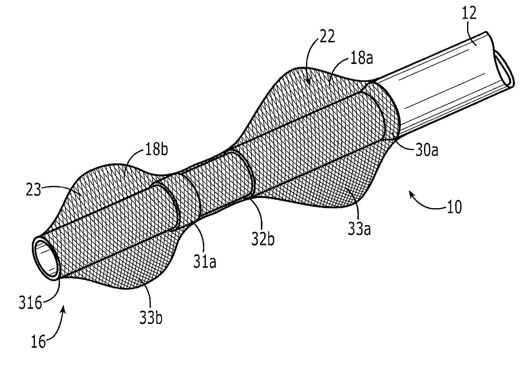
  • Abstract
  • Description
  • Claims
  • Application Information

AI Technical Summary

Benefits of technology

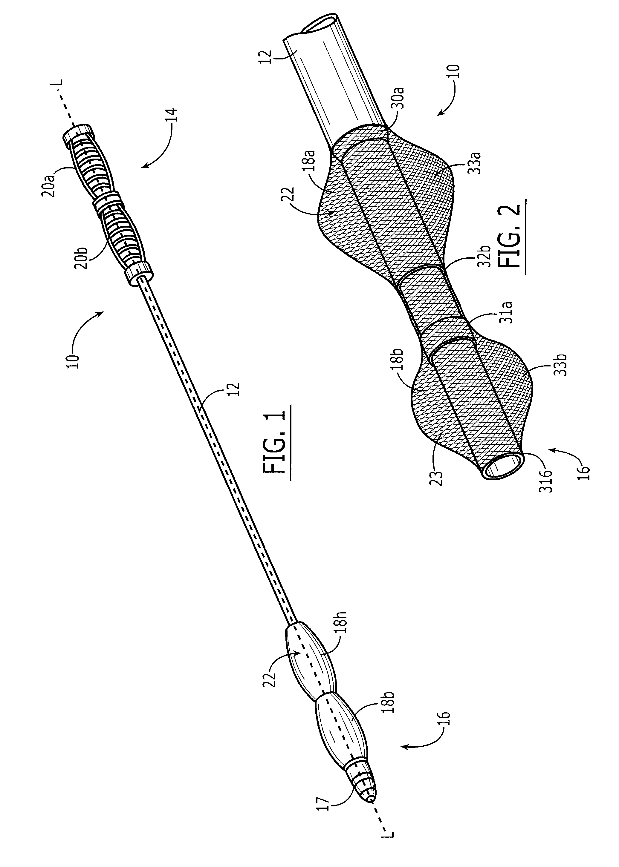
[0004] Described herein are methods and devices for traversing a lumen, such as body lumen. Unlike traditional devices, the embodiments described herein use independently expandable and movable tubing elements to drive the device through a lumen. The tubing elements, in at least one embodiment, are adapted to reduce slippage. For example, the tubing elements can include a traction surface that facilitates gripping of the lumen walls.
[0006] In one aspect, when the tubing elements are radially expanded to contact a lumen wall, they have the ability to grip an internal surface of a lumen without tearing the lumen. For example, the tubing elements can include a traction surface that helps to reduce slippage. In one embodiment, the tubing elements include a rough or porous coating that provides the traction surface.
[0007] Alternatively, or additionally, at least one of the tubing elements is formed from a mesh material that provides the traction surface. Longitudinally contracting (e.g., shortening the length of) the mesh tubing elements causes the tubing elements to radially expand and longitudinally expanding the tubing elements causes the tubing elements to radially contract.
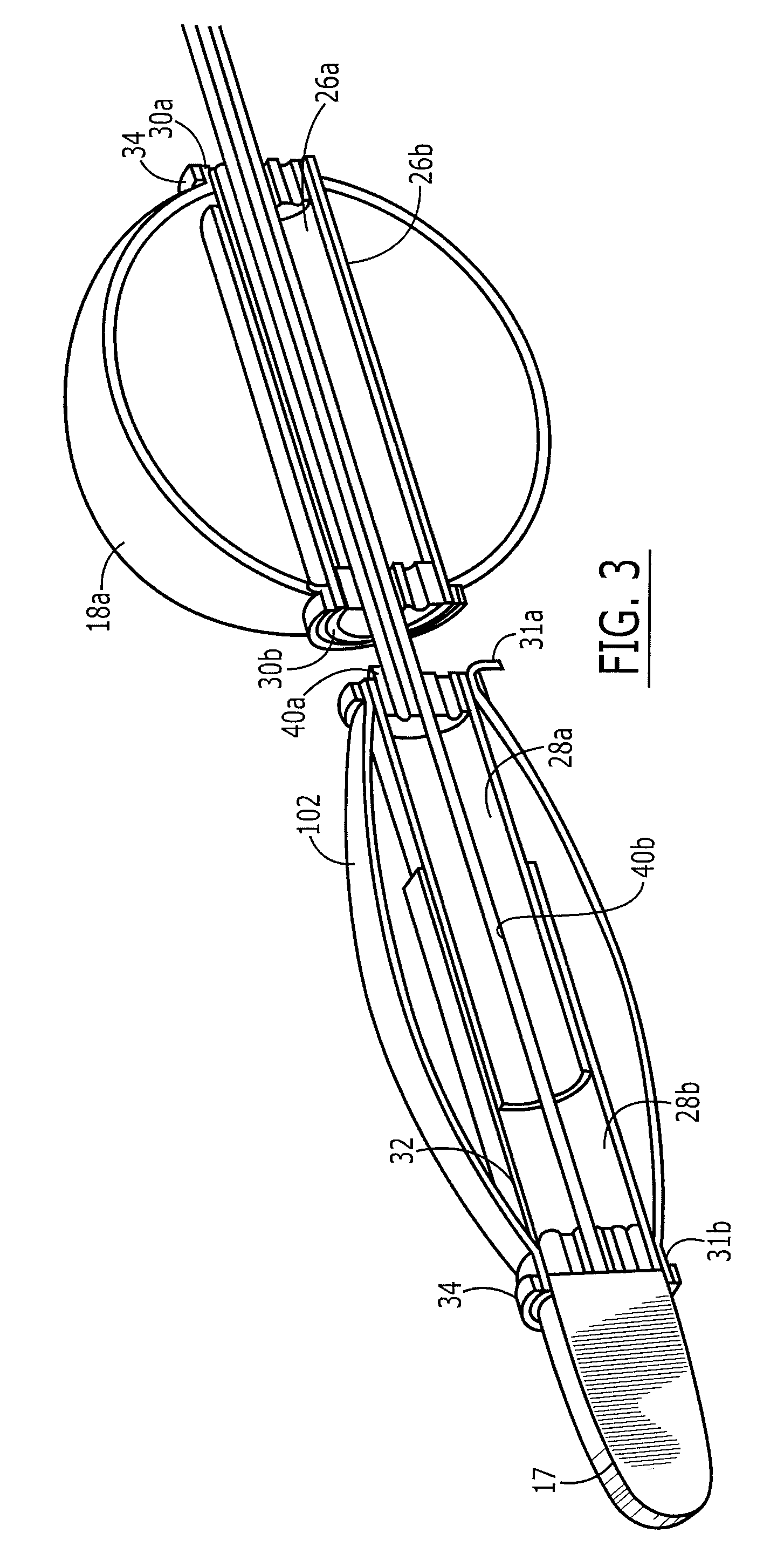
[0008] The distal portion of the device can include first proximal and first distal body members mated with the first tubing element and second proximal and second distal body members mated with the second tubing element. To expand the first tubing element radially, the first proximal body member and the first distal body member can be brought together to shorten the length of the first tubing element. Similarly, to expand the second tubing element, the second proximal body member and the second distal body member can be brought together to shorten the length of the second tubing element. To reverse the process, the proximal and distal body members are moved apart to lengthen the tubing elements.
[0009] In another aspect, the device includes first and second control elements adapted to control expansion and contraction of the tubing elements. For example, proximally positioned control elements can allow a surgeon to remotely control expansion and contraction of distally positioned tubing elements. In addition, the control elements can be adapted to move the tubing elements relative to one another. For example, moving one of the control elements relative to the other control element can move one of the tubing elements relative to the other tubing element.

Problems solved by technology

However, many conventional endoscopes have an inherent problem of access during intraluminal work in the gastrointestinal tract.
Endoscopes are limited in their access since pushing a flexible scope around bends in the GI tract becomes increasingly difficult as the length of the lumen increases.
Other devices, such as balloon-based bowel crawlers, have limits to their successful use due to issues of speed and traction on the internal bowel wall.
That is, it can prove difficult to use the bowel wall to push / pull the device given the need to avoid tearing the gastrointestinal tract and the variations in lumen diameter.

Method used


Image

  • Lumen traversing device
  • Lumen traversing device
  • Lumen traversing device

Examples


Embodiment Construction

[0025] Certain exemplary embodiments will now be described to provide an overall understanding of the principles of the structure, function, manufacture, and use of the devices and methods disclosed herein. One or more examples of these embodiments are illustrated in the accompanying drawings. Those skilled in the art will understand that the devices and methods specifically described herein and illustrated in the accompanying drawings are non-limiting exemplary embodiments and that the scope of the present invention is defined solely by the claims. The features illustrated or described in connection with one exemplary embodiment may be combined with the features of other embodiments. Such modifications and variations are intended to be included within the scope of the present invention

[0026] The present invention generally provides methods and devices for traversing a lumen of a tubular body part, such as the GI tract. In an exemplary embodiment, the methods and devices utilize tu...


PUM


Abstract

Various exemplary methods and devices are provided for traversing a lumen, such as the gastrointestinal tract. The devices can include an elongate body having distally positioned tubing elements and proximally positioned control elements. The tubing elements are adapted for selective and independent radial expansion and contraction and longitudinal movement, such that movement of the tubing elements can drive the device through a lumen. In addition, the tubing elements can include a traction surface to reduce slippage.

Description

BACKGROUND OF THE INVENTION [0001] A variety of medical devices are passed through a lumen of a tubular body part for surgical, diagnostic and / or delivery purposes. An endoscope, for example, is an instrument that is used for visually examining and / or facilitating treatment of a site at an internal body cavity, such as in the gastrointestinal (GI) tract. During a procedure involving use of an endoscope, the instrument must be carefully navigated through the lumen to access the desired site and to avoid perforating the intraluminal wall of the body part. [0002] However, many conventional endoscopes have an inherent problem of access during intraluminal work in the gastrointestinal tract. Endoscopes are limited in their access since pushing a flexible scope around bends in the GI tract becomes increasingly difficult as the length of the lumen increases. Other devices, such as balloon-based bowel crawlers, have limits to their successful use due to issues of speed and traction on the i...

Claims


Application Information

Patent Timeline
Patent Type & Authority Applications(United States)
IPC IPC(8): A61F11/00
CPCA61B1/00082A61B1/01A61B1/273A61B1/31A61B5/6858A61B1/00066
Inventor ORTIZ, MARK S.
Owner ETHICON ENDO SURGERY INC
Learn More