
System and method for retaining vaso-occlusive devices within an aneurysm

a vaso-occlusive device and aneurysm technology, applied in the field of vaso-occlusion, can solve the problems of high undesirable occlusion, specific risk that a portion of the coil might migrate out of the aneurysm entrance zone and into the feeding vessel, and aneurysms present a particularly acute medical risk

Inactive Publication Date: 2007-05-10
STRYKER EURO OPERATIONS HLDG LLC
View PDF17 Cites 143 Cited by
  • Summary
  • Abstract
  • Description
  • Claims
  • Application Information

AI Technical Summary

Benefits of technology

[0016] In accordance with a first aspect of the present invention, at least one of the proximal and distal ends of the mesh-like structure is configured to be inserted through the aneurysmal neck when in an undeployed state, and configured to flare open and expand against at least a portion of the aneurysmal inner wall when in a deployed state. Having a flared open end may advantageously allow the device to conform to the shape of the aneurysm.
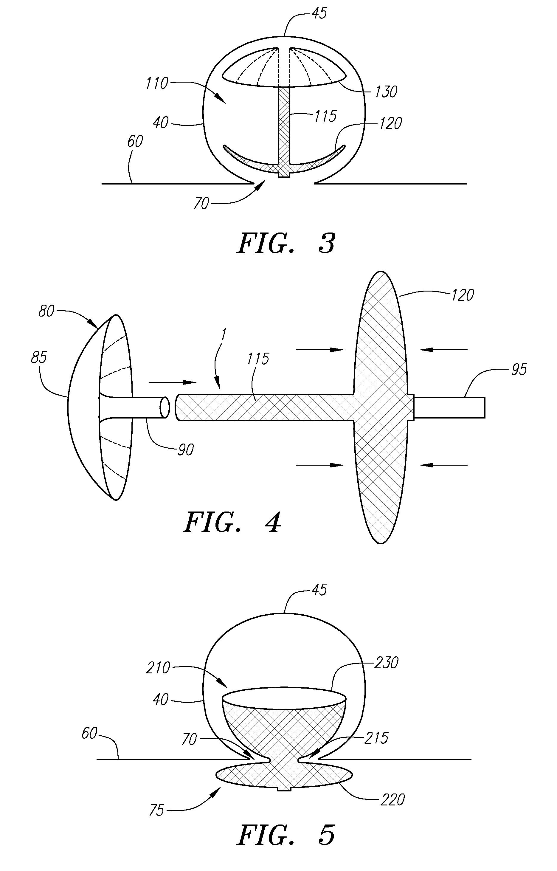
[0017] In accordance with another aspect of the present invention, the distal end of the mesh-like structure may be configured to be inserted through the aneurysmal neck when in an undeployed state and configured to expand into a retainer against at least a portion of the aneurysmal inner wall when in a deployed state. The proximal end may be configured to expand into an anchor just outside of the aneurysm to secure the mesh-like structure in position.

Problems solved by technology

Often these aneurysms are the site of internal bleeding and stroke.
As noted above, aneurysms present a particularly acute medical risk due to the dangers of potential rupture of the thin wall inherent in such aneurysms.
However, after, or perhaps during, delivery of the coil into the aneurysm, there is a specific risk that a portion of the coil might migrate out of the aneurysm entrance zone and into the feeding vessel.
The presence of the coil in that feeding vessel may cause a highly undesirable occlusion there.
Also, there is a quantifiable risk that the blood flow in the vessel and aneurysm may induce movement of the coil farther out of the aneurysm, resulting in a more developed embolus in the feeding vessel.
One type of aneurysm, commonly known as a “wide neck aneurysm,” is known to present particular difficulty in the placement and retention of vaso-occlusive coils, because vaso-occlusive coils lacking substantial secondary shape strength may be difficult to maintain in position within an aneurysm no matter how skillfully they are placed.
In some cases, it may still be desirable to deploy vaso-occlusive coils with such a device, but the bulbous body of the vaso-occlusive device does not provide much space within the aneurysm to allow for insertion and deployment of the coils.

Method used


Image

  • System and method for retaining vaso-occlusive devices within an aneurysm
  • System and method for retaining vaso-occlusive devices within an aneurysm
  • System and method for retaining vaso-occlusive devices within an aneurysm

Examples


Embodiment Construction

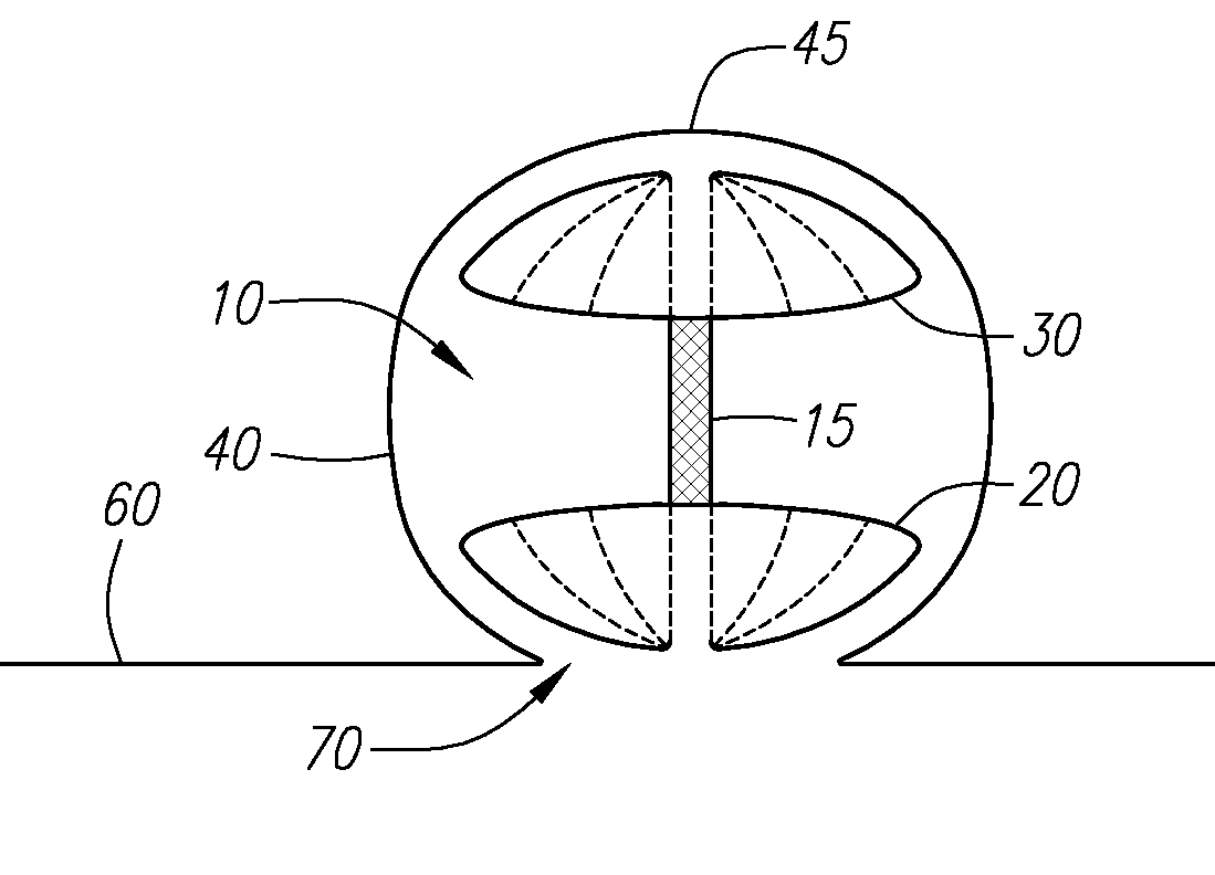
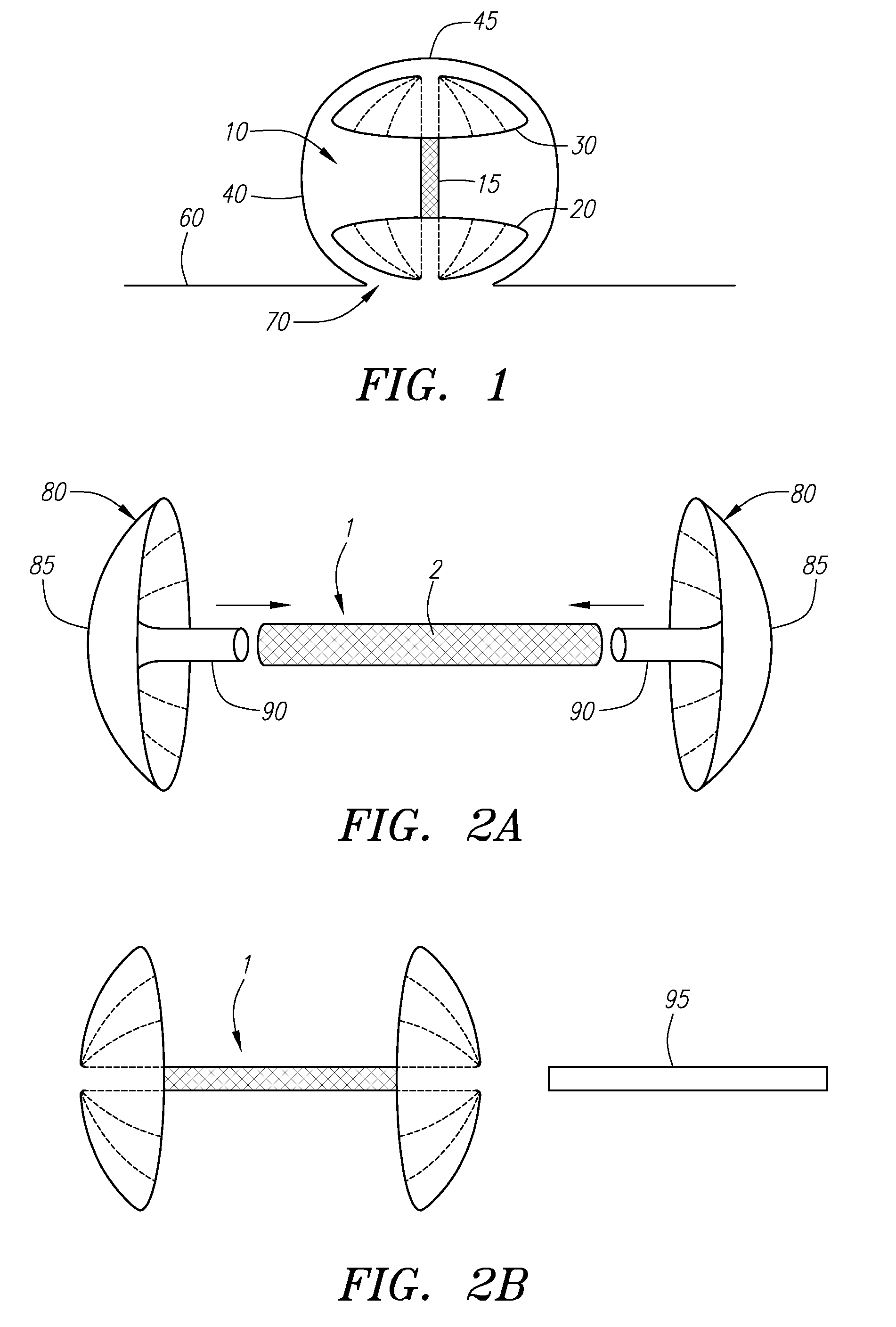
[0031] Turning to FIG. 1, a vaso-occlusive element 10 constructed in accordance with a preferred embodiment of the present invention is shown completely deployed within an aneurysm 40 of a blood vessel 60. The aneurysm 40 is shown with an oppositely disposed neck 70 and dome 45. When deployed in its secondary shape, i.e., its deployed shape, the vaso-occlusive element 10 generally includes a central tubular element 15 and proximal 20 and distal 30 ends that are flared open into “umbrella” shapes. As illustrated, the flared opened ends 20 / 30 advantageously conform to the shape of the aneurysm 40. The diameter of the proximal end 20 of the vaso-occlusive element 10 is larger than the neck 70, and thus the proximal end 20 may completely cover the neck 70.

[0032] As will be described in further detail below, the vaso-occlusive element 10 is manufactured from a relatively dense braid. In this manner, the proximal end 20 may densely cover the neck 70 and function as a retainer. Thus, fine...


PUM


Abstract

The present invention is directed to systems for occluding an aneurysm having an aneurysmal neck and an aneurysmal inner wall. Generally, a device in accordance with the present invention includes a mesh-like structure that is integrally composed of a shape-memory alloy such as NiTi. The device is deployed within the aneurysm through the aneurysmal neck. The device is configured to be in a deployed state and an undeployed state, and is configured to transition from the undeployed state to the deployed state by exposure to a higher temperature and / or by being unconstrained. The device may function to retain finer vaso-occlusive devices such as vaso-occlusive coils and / or embolic liquids. Furthermore, the device itself may function as a vaso-occlusive device.

Description

RELATED APPLICATION DATA [0001] The present application is a continuation of co-pending U.S. patent application Ser. No. 10 / 121,980 filed Apr. 12, 2002, which is hereby incorporated by reference.FIELD OF THE INVENTION [0002] The present invention relates generally to vaso-occlusion, and more particularly to systems and methods for retaining vaso-occlusive devices within an aneurysm. BACKGROUND OF THE INVENTION [0003] Different implantable medical devices have been developed for treating a number of ailments associated with body lumens. In particular, occlusive devices are useful in filling vascular or other body spaces. Some body spaces, such as vascular aneurysms, are formed due to a weakening in the wall of an artery. Often these aneurysms are the site of internal bleeding and stroke. A variety of different embolic agents are known to be, at least arguably, suitable for treatment of these anomalies. These treatments are commonly known as “artificial vaso-occlusion.”[0004] Over the...

Claims


Application Information

Patent Timeline
IPC IPC(8): A61B17/08A61B17/00A61B17/12A61F2/06
CPCA61B17/12022A61B17/12113A61B17/12172A61B2017/12063A61F2/06
Inventor WALLACE, MICHAELEDER, JOSEPHGERBERDING, BRENT C.
Owner STRYKER EURO OPERATIONS HLDG LLC
Learn More