Drying apparatus

a technology of drying apparatus and drying chamber, which is applied in the direction of domestic cooling apparatus, lighting and heating apparatus, furniture, etc., can solve the problems of deteriorating heating performance, inability to control the superheat value, and risk of compressor damage, so as to shorten the drying time

Inactive Publication Date: 2007-05-17
PANASONIC CORP
View PDF22 Cites 59 Cited by
  • Summary
  • Abstract
  • Description
  • Claims
  • Application Information

AI Technical Summary

Benefits of technology

[0046] According to the drying apparatus of the present invention, it is possible to control the superheat value to a target value in the drying process. Therefore, it is possible to avoid liquid back to the compressor that has been a conventional problem, and to shorten the drying time.

Problems solved by technology

However, the cloth drier shown in FIG. 11 cannot control a superheat value that changes in the drying process.
Therefore, in the case where the compressor 25 carries out compression of the liquid refrigerant, a risk that the compressor is damaged may occur.
On the other hand, in the case where the superheat value becomes too small (SH Small), compressor discharge temperature is lowered, and heating performance is deteriorated, whereby the heat pump performance is deteriorated.

Method used


Image

  • Drying apparatus
  • Drying apparatus
  • Drying apparatus

Examples


first embodiment

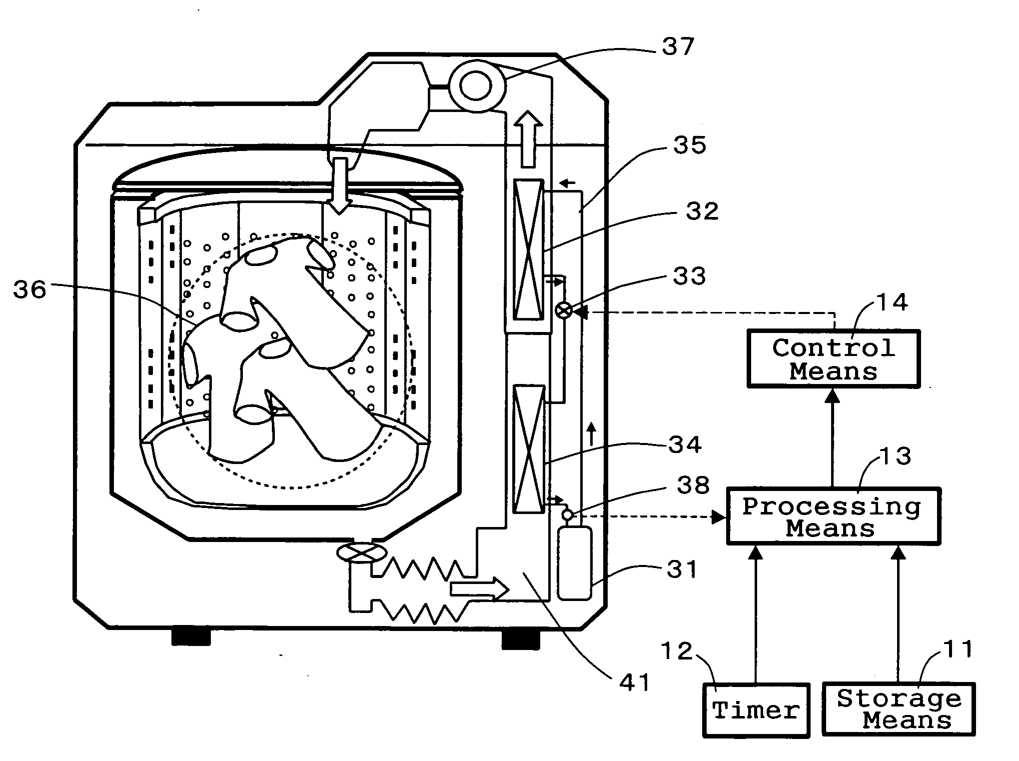
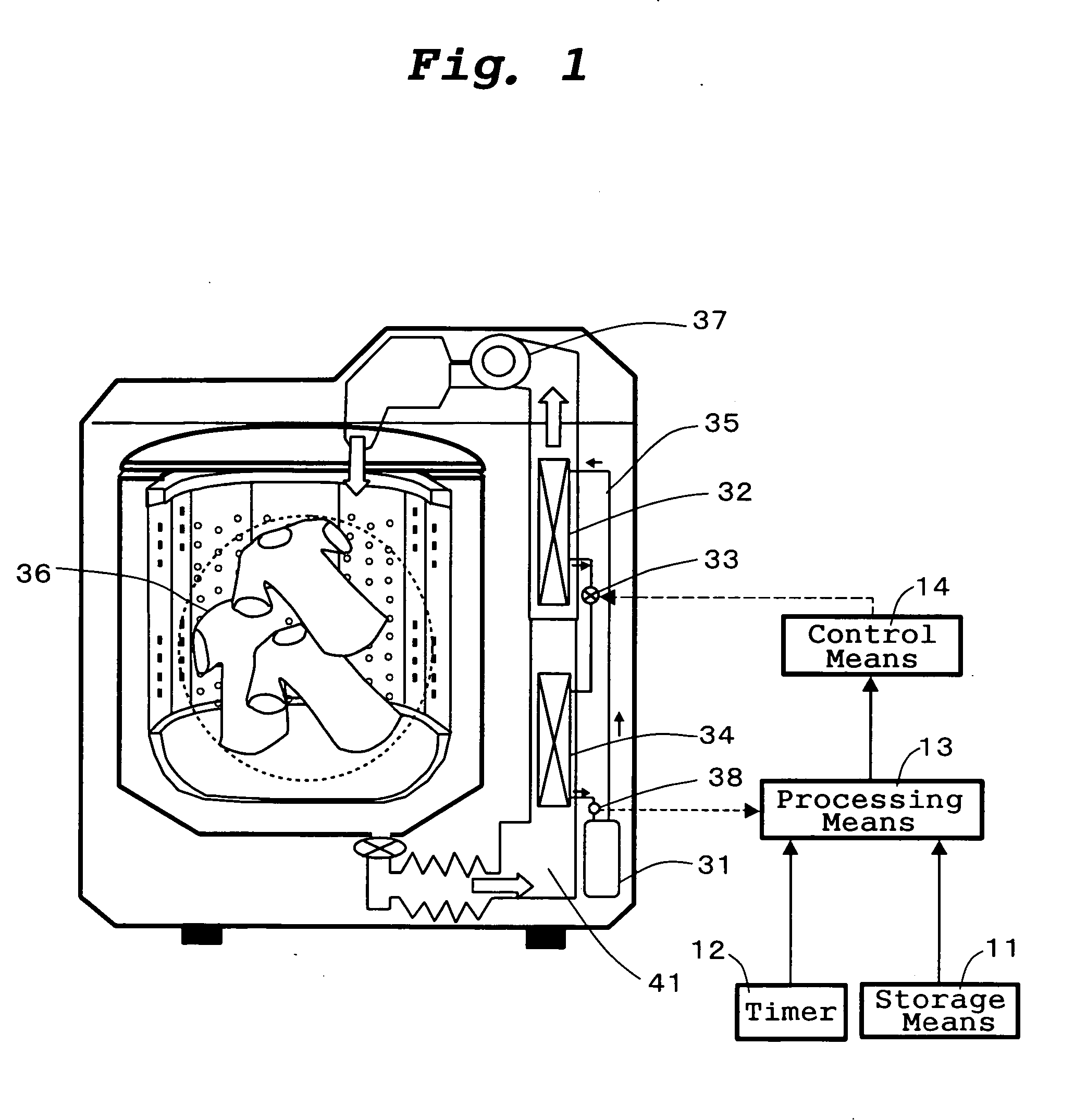
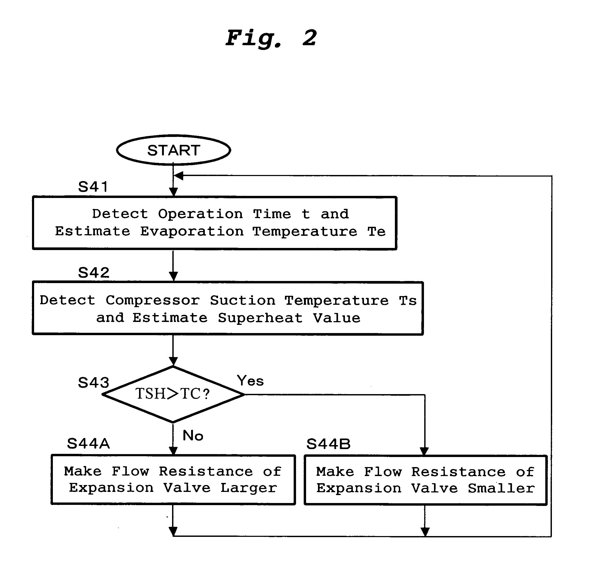
[0058] Preferred embodiments of the present invention will be explained with reference to the appending drawings. FIG. 1 shows a structure of a drying apparatus of a first embodiment according to the present invention. FIG. 2 shows a control flowchart of the drying apparatus of the first embodiment.

[0059] Referring to FIG. 1, a drying apparatus of the present embodiment includes a heat pump apparatus, and an air channel 41 in which the heat pump apparatus is used as a heat source for drying a subject to be dried and drying air is circulated and reused. The heat pump apparatus includes: a compressor 31 for compressing a refrigerant; a radiator 32 for condensing the refrigerant by heat radiation effect to heat the drying air; an expansion valve 33 for reducing the pressure of the refrigerant; and an evaporator 34 for evaporating the refrigerant by endothermic effect to dehumidify the drying air. These elements of the heat pump apparatus are connected in series to one another through ...

second embodiment

[0073]FIG. 3 shows a structure of a drying apparatus of a second embodiment according to the present invention. FIG. 4 is a control flowchart of the drying apparatus of the second embodiment. In this regard, in the following explanation for the second embodiment, the same structures as those of the first embodiment are designated with the same symbols, explanation thereof will be omitted, and the structures of the second embodiment which are different from those of the first embodiment will be explained.

[0074] The drying apparatus of the present embodiment includes a second temperature sensor 39 for detecting the refrigerant temperature between the outlet of an expansion valve 33 and the inlet of an evaporator 34 in addition to the structure of the drying apparatus of the first embodiment, and processing means calculates a superheat value based on the difference between the detected values of a first temperature sensor 38 and the second temperature sensor 39. Further, a plurality o...

third embodiment

[0079]FIG. 5 shows a structure of a drying apparatus of a third embodiment according to the present invention. FIG. 6 is a control flowchart of the drying apparatus of the third embodiment. In this regard, in the following explanation for the third embodiment, the same structures as those of the second embodiment are designated with the same symbols, explanation thereof will be omitted, and the structures of the second embodiment which are different from those of the second embodiment will be explained.

[0080] The drying apparatus of the present embodiment includes a third temperature sensor 40 for detecting the temperature of the refrigerant between the outlet of a compressor 31 and the inlet of an expansion valve 33 in addition to the structure of the drying apparatus of the second embodiment. Control means 14 controls flow resistance of the expansion valve 33 using the difference (that is, a superheat value) between the detected values of a first temperature sensor 38 and a secon...


PUM


Abstract

It has been difficult to operate a drying apparatus in a stable and high-efficiency state where a superheat value is changed in a drying process. A drying apparatus includes: a first temperature sensor 38 which detects the temperature of a refrigerant between the outlet of an evaporator 34 and the inlet of a compressor 31; and control means 14 for controlling a superheat value by changing flow resistance of an expansion valve 33 based on a detected value of the first temperature sensor 38. The control means 14 controls the superheat value in the drying process to become a target value.

Description

TECHNICAL FIELD [0001] The present invention relates to a drying apparatus used for drying clothing or bathroom, or used for dehumidify a room. BACKGROUND OF THE INVENTION [0002] As a conventional drying apparatus, there is a cloth drier in which a heat pump apparatus is used as a heat source and drying air is circulated (see patent document 1, for example). FIG. 11 shows a structure of the conventional drying apparatus described in the patent document 1. [0003] In the drying apparatus (cloth drier) shown in FIG. 11, a rotation drum 2 is used as a drying room. The rotation drum 2 is provided in a body 1 of the clothing dryer so as to rotate freely. The rotation drum 2 is driven by a motor 3 through a drum belt 4. Further, a blower 22 is driven by the motor 3 through a fan belt 8. Drying air is sent from the rotation drum 2 to a circulation duct 18 through a filter 29 and a rotation drum-side air intake 10 by the blower 22. [0004] Further, the heat pump apparatus is provided with: an...

Claims


Application Information

Patent Timeline
Patent Type & Authority Applications(United States)
IPC IPC(8): F25D17/04F26B3/00F25B49/00D06F58/02D06F58/20D06F58/24D06F58/28F25B1/00F25B9/00F26B21/00F26B21/08
CPCD06F58/206D06F58/28D06F2058/287F25B9/008F25B2309/061F25B2600/2513F25B2700/21151F25B2700/21152F26B21/086D06F2103/50D06F2105/26D06F58/46D06F58/38D06F2103/38
Inventor TAMURA, TOMOICHIROYAKUMARU, YUUICHIHONMA, MASAYANISHIWAKI, FUMITOSHI
Owner PANASONIC CORP
Why Eureka
Try Eureka