
Method of accurately positioning anchor bolt to foundation by swing-type anchor bolt

a technology of swing-type anchor bolts and anchor bolts, which is applied in the direction of construction, foundation engineering, etc., can solve the problems of inefficient work, inconvenient and low flexibility on the building site, and achieves a high degree of accuracy and simple procedure. , the effect of easy adjustment of the height of the anchor bolt to be positioned and installed

Inactive Publication Date: 2007-05-17
MATSUMOTO ARCHITECT
View PDF0 Cites 30 Cited by
  • Summary
  • Abstract
  • Description
  • Claims
  • Application Information

AI Technical Summary

Benefits of technology

[0049] According to the first, second, third, and fourth aspects of the present invention, accurate and quick positioning of the anchor bolt on the foundation is realized in a simple procedure using members of an extremely simple structure without using a temporary reference construction.
[0050] In addition by securing the verticality of the anchor bolt or the reference center shaft using the plummet instrument, the immovable center mark on the leveling concrete can be moved to the top end of the foundation with a high degree of accuracy.

Problems solved by technology

Therefore, installation of the bed-sill to the top end of the foundation is enabled only after such a troublesome work, and is a very inefficient work.
In prefabricated buildings or steel-frame buildings, superstructures are fabricated in a factory, and hence flexibility at the building site is extremely low.
Since this method must be completed within a relatively short time until concrete is hardened, the procedures are hurriedly performed, and hence measurement may be inaccurate.
In addition, with this method, the temporary reference construction which serves as a reference of measurement can be displaced with a slight external force, and hence there is a problem such that the reliability of the temporary reference construction which serves as a reference cannot be secured.
Furthermore, there is also a problem such that the temporary reference construction becomes an obstacle of various works.
Therefore, the problems described above are not solved at all.
However, it seems that required positioning accuracy of the anchor bolt cannot be achieved sufficiently in a practical sense.
The concrete form for building the foundation is, as long as it is the one currently used, not able to avoid slight displacement due to a high pressure exerted when casting concrete.
Therefore, in spite of increase of positioning accuracy in support of the anchor bolt supporting member itself, displacement occurs on the side of concrete form and, accordingly, displacement of the anchor bolt supporting member itself may be resulted.
Furthermore, the high pressure exerted when casting concrete is also exerted to the anchor bolt which is supported by the supporting member or the like.
Therefore, the supporting member cannot support the pressure, and hence slight displacement cannot be avoided unless it has a substantially solid structure.
Therefore, with the technique in which the anchor bolt is fixed to the concrete form via the supporting means as shown in Patent Documents 2 and 3, the positioning accuracy cannot be improved sufficiently.
However, in such a structure, the longer the anchor bolt becomes, the higher strength of the frame is required.
Therefore, the cross-section of the frame further increases, and the weight also increases correspondingly, whereby workability is deteriorated and hence increase in cost cannot be avoided.
However, such reinforcing steel is displaced easily and significantly when casting concrete.

Method used


Image

  • Method of accurately positioning anchor bolt to foundation by swing-type anchor bolt
  • Method of accurately positioning anchor bolt to foundation by swing-type anchor bolt
  • Method of accurately positioning anchor bolt to foundation by swing-type anchor bolt

Examples


example 1

[0220] Example 1 relates to a method of positioning an anchor bolt to be installed in a concrete foundation of a wooden building and, in particular is suitable for the case of installing an anchor bolt which is required to have a high accuracy such as a hold-down anchor bolt, an anchor bolt to be installed at a portion close to a bracing, or an anchor bolt to be installed at a bed-sill joint portion. In addition, it is also suitable as a method used for positioning of all other types of anchor bolts, as a matter of course.

[0221] In a first step, a center mark for the anchor bolt to be installed is positioned and indicated on leveling concrete using this method. The leveling concrete is to be disposed within a required range in an area to establish the foundation in advance.

[0222] The center mark for the anchor bolt as described above is to be positioned directly from a reference center of a building which is separately set and indicated on the leveling concrete, and indicated with...

example 2

[0243] Example 2 relates to the method of positioning the anchor bolt 6 in the case in which the foundation is constructed by casting concrete for the base portion and the rising portion in two steps.

[0244] The procedure until the center marks ca, ca . . . , cs, cs . . . are positioned and indicated on the leveling concrete 2 is exactly the same as Example 1.

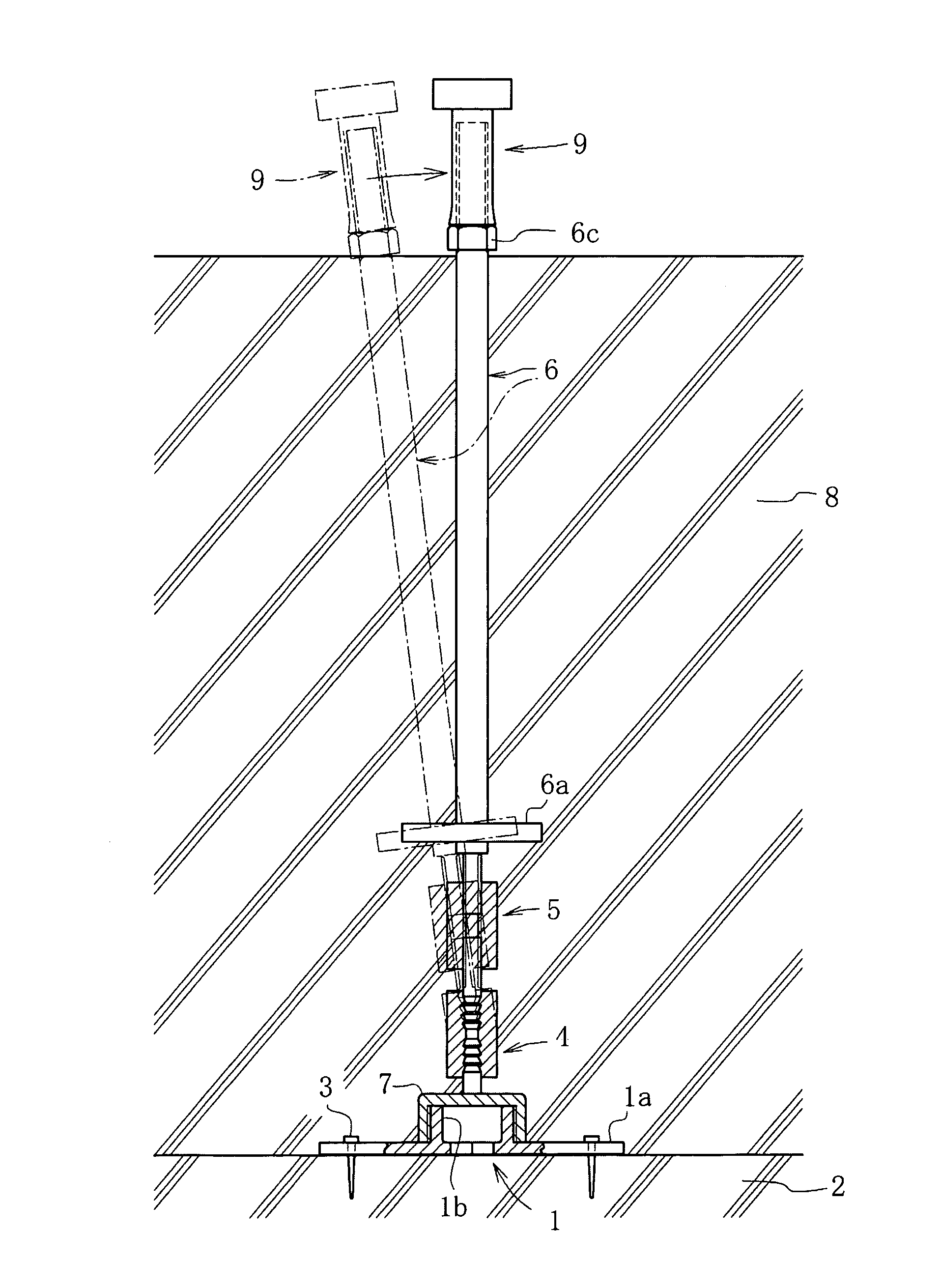
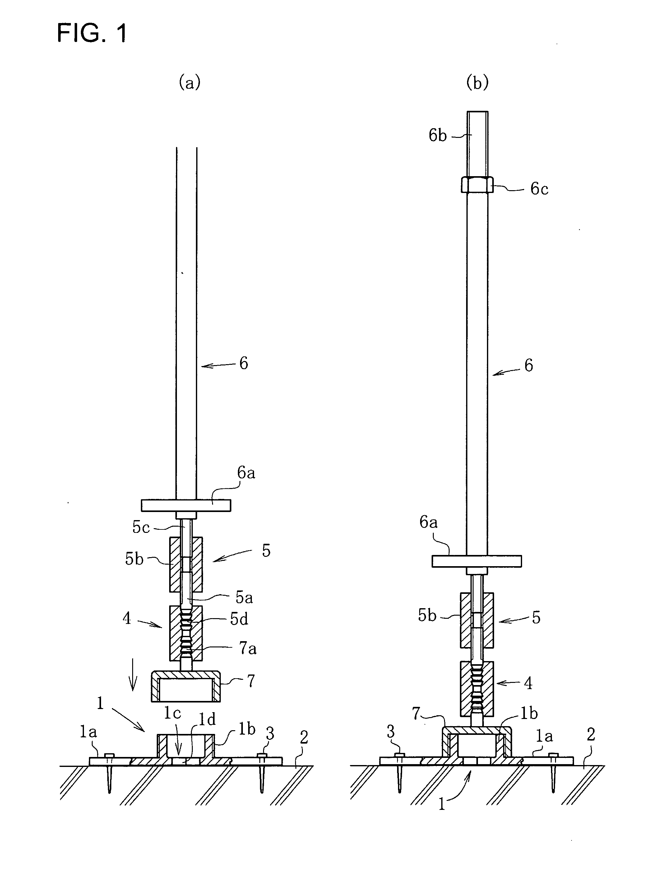
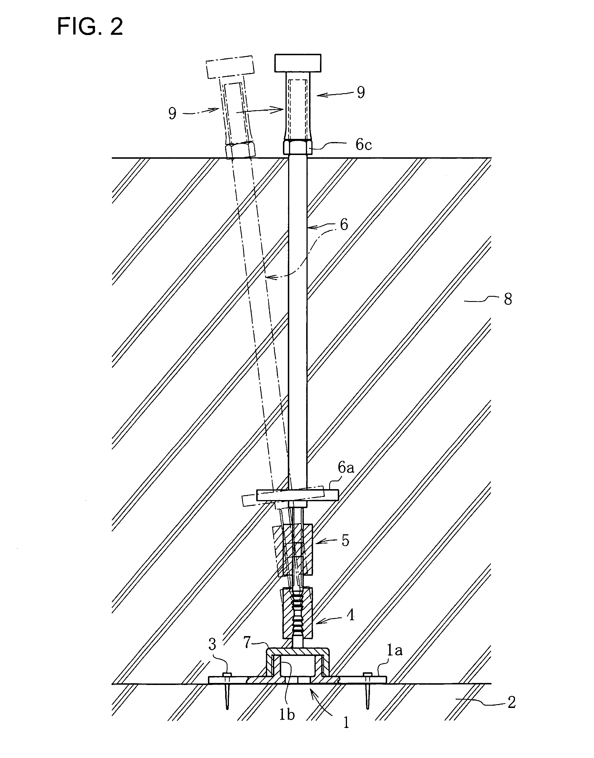
[0245] In Example 2 as well, the mounting member 1 having the hollow bolt 1b with the base seat 1a which is the same as Example 1 is installed so as to match the corresponding center mark ca. The method of positioning the mounting member 1 in this case is the same as those described in Example 1. However, in Example 2, the more accurate verticality of the hollow bolt 1b which extends upright from the mounting member 1 is required. In this case, the base seat 1a is positioned, and is temporarily fixed as shown in FIG. 6(a), and then the ball head lock nut 7 with an extension shaft 7b extending upright from an upper surface ther...

example 3

[0254] Example 3 relates to a method of positioning the anchor bolt 6 in the case in which the foundation is constructed in two steps by casting concrete for the base portion and the rising portion as in the case of Example 2, and is different from Example 2 in the process after positioning and indication of the center marks ca, ca . . . and cs, cs . . . on the leveling concrete 2 until upright disposition and fixation of the extension shaft 7b. Since the different point is only the process described above, only the different point will be described.

[0255] As shown in FIG. 10(a), a drill d is aligned with the corresponding center mark ca on the leveling concrete 2 and a mounting hole hm is drilled. Then, as shown in FIG. 10(b), a plug member p is press fitted and fixed in the mounting hole hm. Subsequently, as shown in FIG. 10(c), a screw member 1e is provided as the anchor bolt mounting means at the lower end of the extension shaft 7b, and the extension shaft 7b provided with a fl...


PUM


Abstract

To enable realization of accurate positioning of an anchor bolt to a foundation with a simple procedure using a member of an extremely simple structure without using a temporary reference construction. An anchor bolt 6 is accurately positioned and installed on leveling concrete 2 by fixedly installing a base seat 1a of a mounting member 1 so as to be aligned with a center mark for the anchor bolt positioned and indicated thereon, disposing the anchor bolt 6 upright on a hollow bolt 1b via a hinge member 4 and a turn buckle member 5, then casting concrete for a base portion and a rising portion of the foundation simultaneously, adjusting the anchor bolt 6 which is inclined at the hinge member 4 being bent due to the casting pressure into a vertical state while measuring with a plummet instrument before the concrete is hardened, and maintaining the anchor bolt 6 in the vertical state by a verticality holder until the concrete is hardened.

Description

TECHNICAL FIELD [0001] The present invention relates to a method of accurately positioning an anchor bolt to be embedded in foundation concrete of various building structures by a swing-type anchor bolt. BACKGROUND ART [0002] In foundations of various building structures, it is necessary to provide an anchor bolt for firmly connecting the foundation and building frame of an upper structure to be installed thereon at the time of construction. The anchor bolt is a member whose lower portion is to be embedded in the foundation in a state in which an upper portion thereof projected from an upper surface of the foundation, as is needless to say. [0003] In residential construction built by a conventional construction method, through holes for anchor bolts opening on bed-sills have been formed by measuring positions of the anchor bolts extending upright from a top end of the foundation individually, marking the positions on groundwork before installation, and drilling the marked positions ...

Claims


Application Information

Patent Timeline
Patent Type & Authority Applications(United States)
IPC IPC(8): E02D27/00E02D27/32
CPCE02D27/32E02D27/00
Inventor MATSUMOTO, TAKASHI
Owner MATSUMOTO ARCHITECT
Features
  • Generate Ideas
  • Intellectual Property
  • Life Sciences
  • Materials
  • Tech Scout
  • Unparalleled Data Quality
  • Higher Quality Content
  • 60% Fewer Hallucinations
Learn More