

Pressure control valve for refrigeration cycle
- Summary
- Abstract
- Description
- Claims
- Application Information
AI Technical Summary
Benefits of technology
Problems solved by technology
Method used
Image

Examples
Embodiment Construction
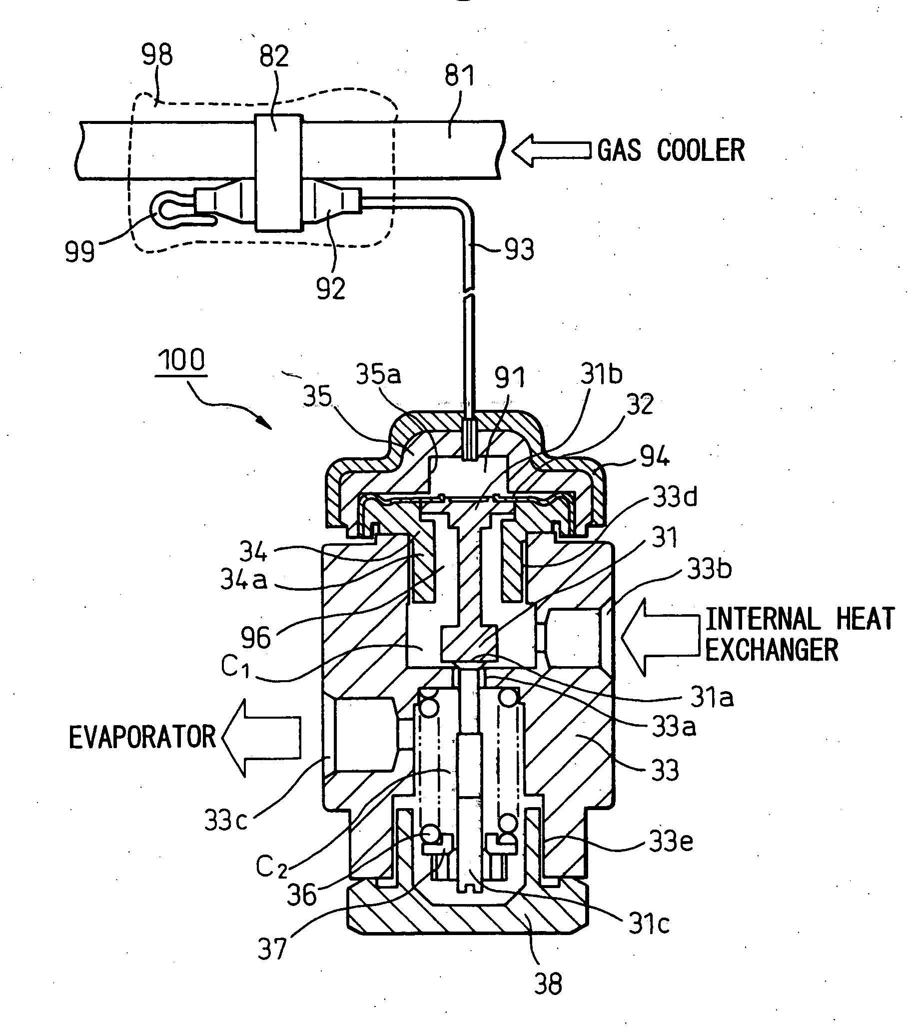
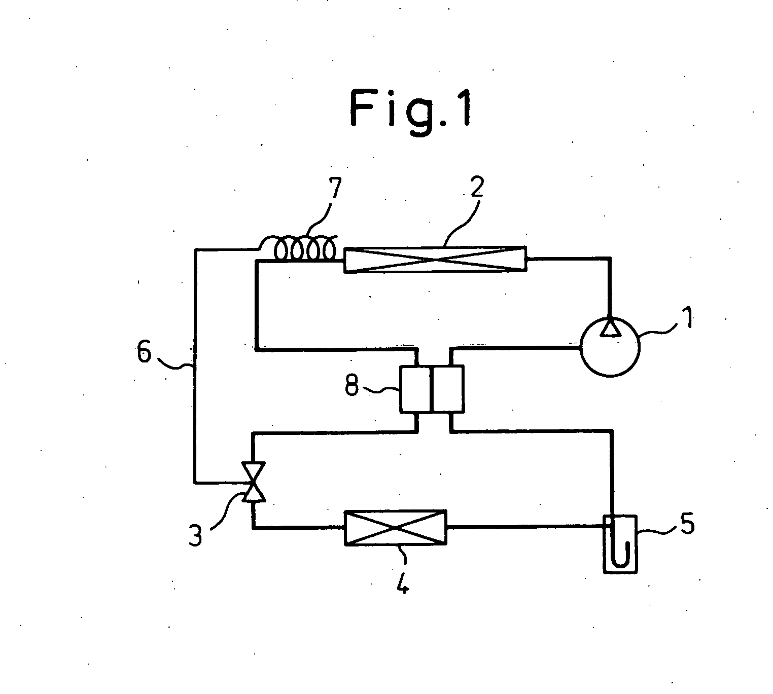
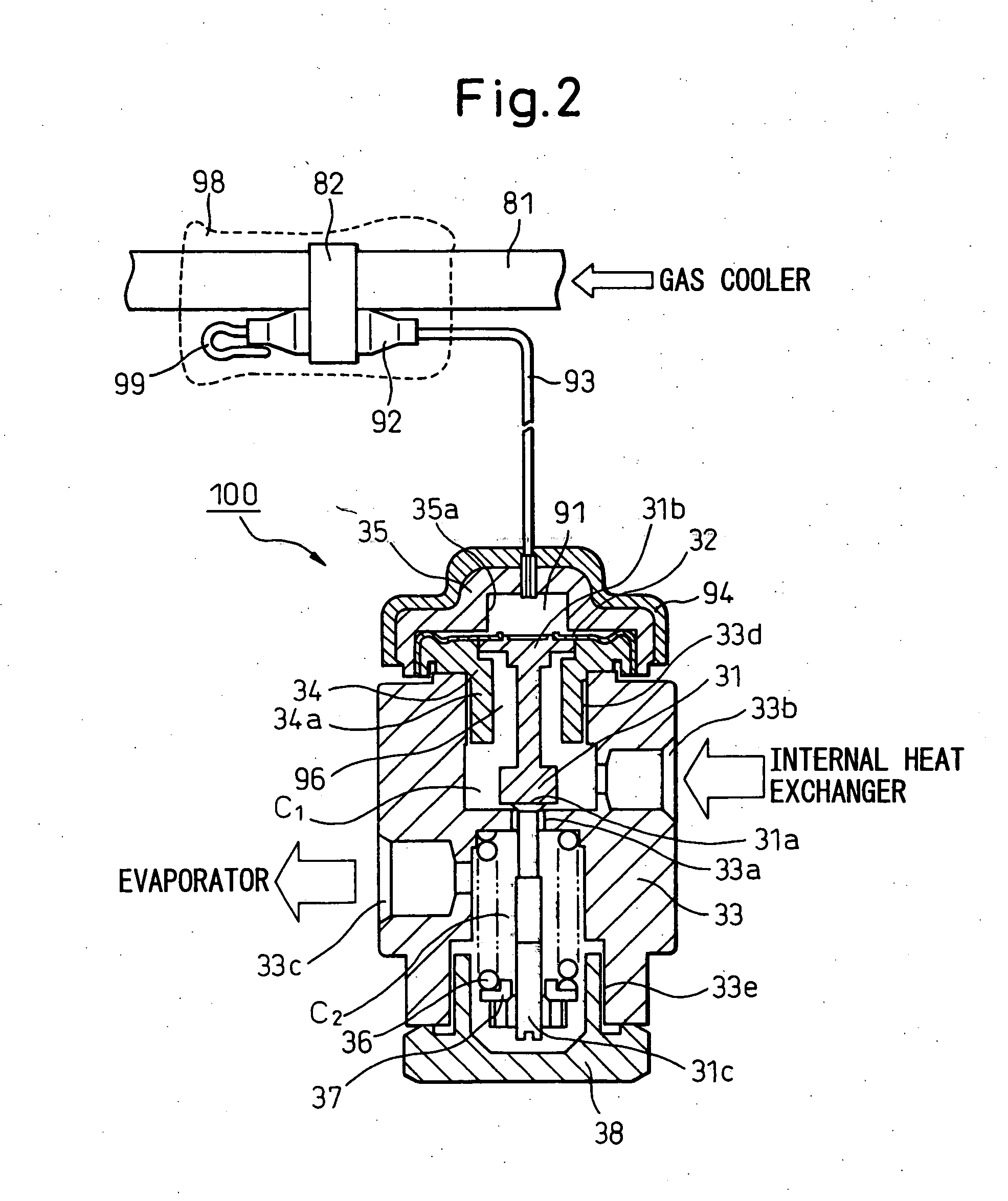
[0030] Below, embodiments of the present invention will be explained with reference to the drawings. FIG. 1 shows a refrigeration cycle using an internal heat exchanger; FIG. 2 is a cross-sectional view of a first embodiment according to the present invention (feeler bulb type); FIG. 3 is cross-sectional view of a second embodiment according to the present invention (box type); FIG. 4 shows a refrigeration cycle using an internal heat exchanger; FIG. 5 is a cross-sectional view of a third embodiment according to the present invention (box type, sensing valve inlet refrigerant temperature); FIG. 6 is a cross-sectional view of a fourth embodiment according to the present invention (box type+heat insulating packing); FIG. 7 is a cross-sectional view of a fifth embodiment according to the present invention (box type+cap); FIG. 8 is a schematic view of a feeler bulb and another volume part; FIG. 9 is a view showing changes in control pressure of a sealed refrigerant with respect to the v...
PUM
 Abstract
Description
Claims
Application Information