Charging method, charging circuit, and charging device

a charging circuit and secondary battery technology, applied in electric vehicles, electric power, transportation and packaging, etc., can solve the problems of shortening the life affecting the discharge current of the lithium ion secondary battery, and affecting the discharge current of the secondary battery, so as to suppress overcharging and reduce the charging current

Inactive Publication Date: 2007-05-17
MATSUSHITA ELECTRIC WORKS LTD
View PDF3 Cites 33 Cited by
  • Summary
  • Abstract
  • Description
  • Claims
  • Application Information

AI Technical Summary

Benefits of technology

[0009] The above arrangement enables to reduce the charging current immediately after the charging start, and to suppress overcharging which may occur in start of charging the secondary battery in a full charge condition or a near-full-charge condition.

Problems solved by technology

Overcharging such a secondary battery may cause breakage of a battery pack or shorten the life of the secondary battery.
In particular, an adverse effect by overcharging is serious in the lithium ion secondary batteries.
The less flow of the charging current, however, may increase a charging time.
As a result, overcharge may occur in the secondary battery incorporated with the aforementioned charging circuit.
This may cause overcharging of the secondary battery.

Method used


Image

  • Charging method, charging circuit, and charging device
  • Charging method, charging circuit, and charging device
  • Charging method, charging circuit, and charging device

Examples


first embodiment

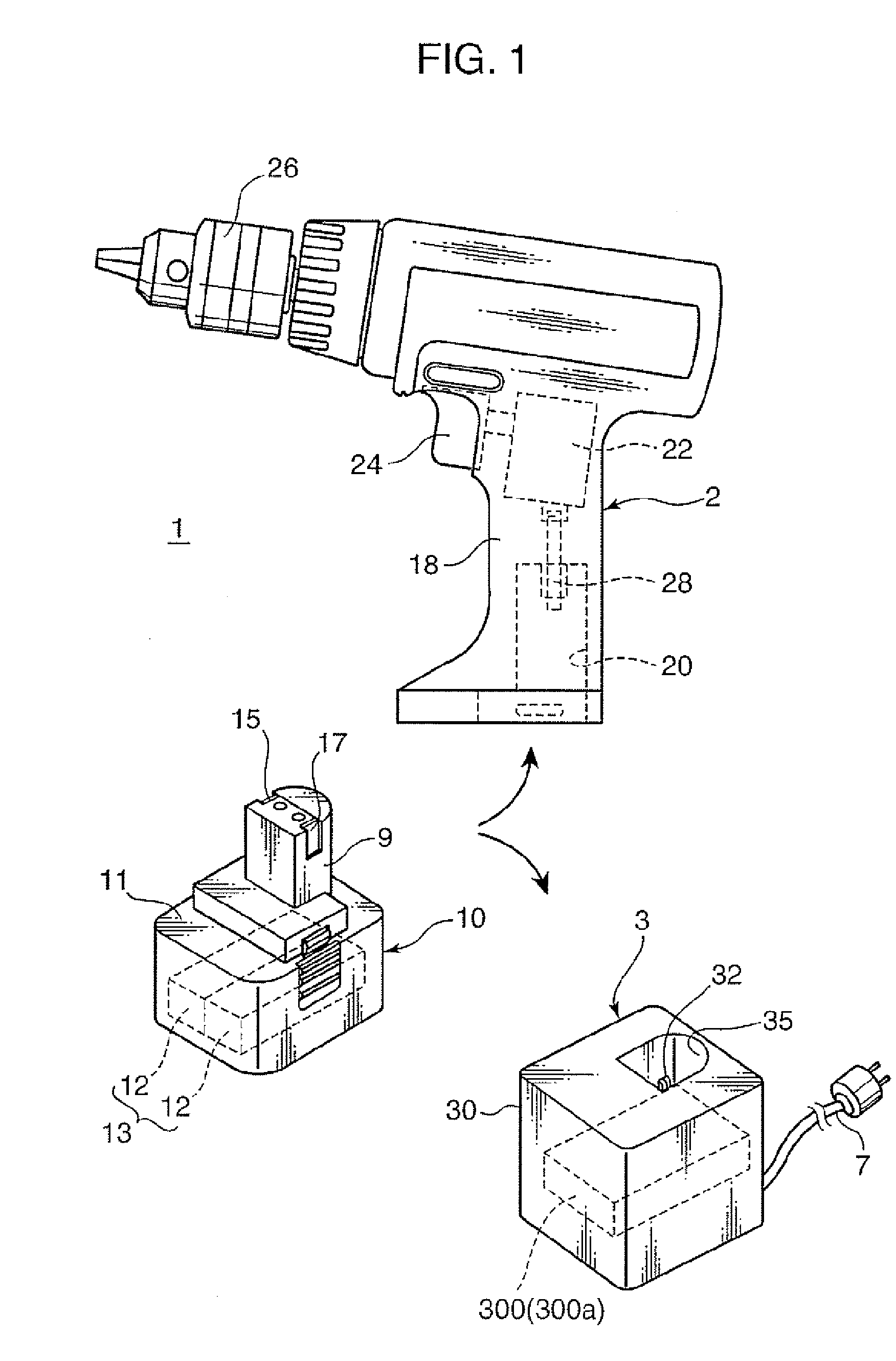
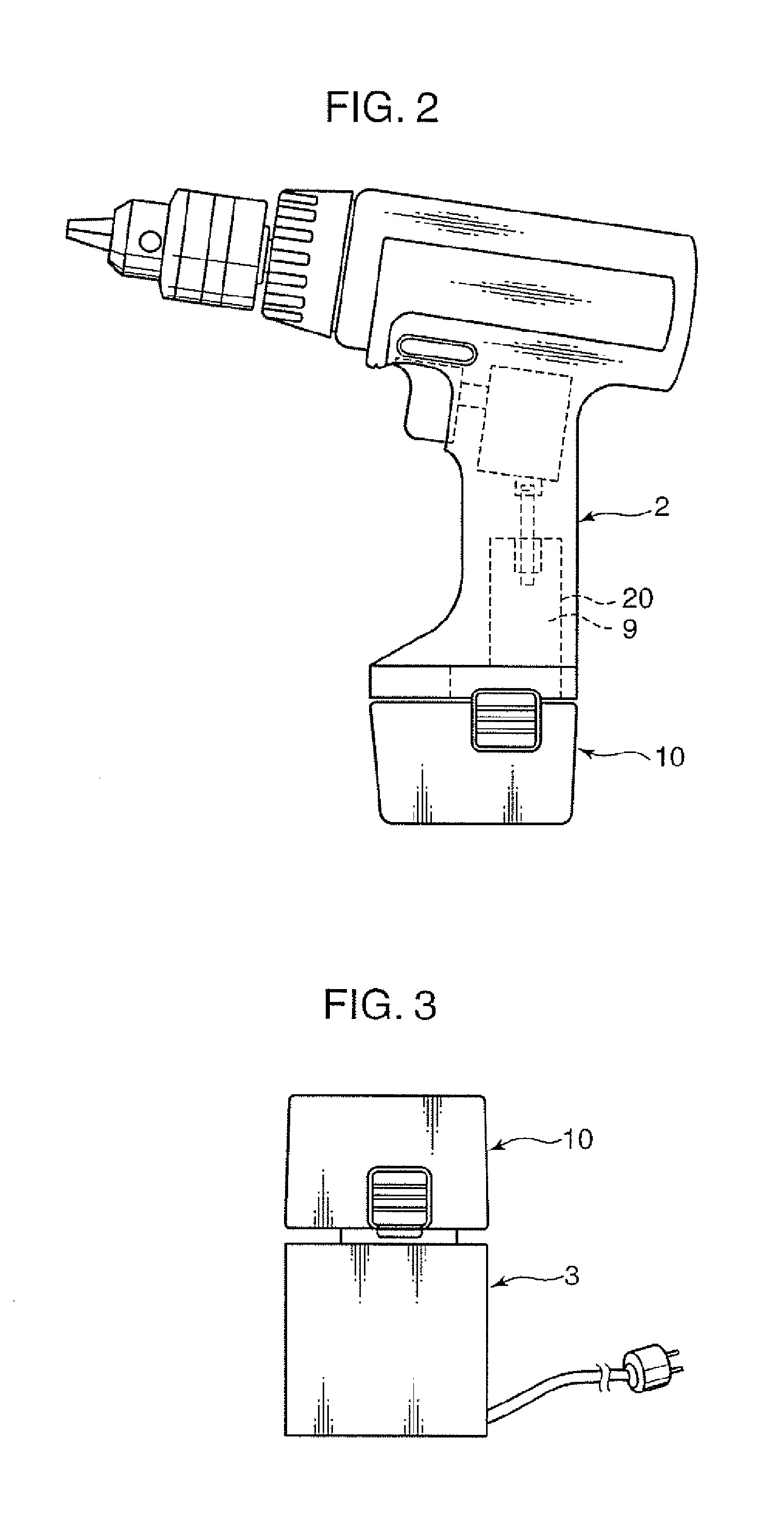
[0024]FIG. 1 is an external view showing a charging device incorporated with a charging circuit according to the first embodiment of the invention, and essential parts of a rechargeable electric tool kit equipped with the charging device. Referring to FIG. 1, the rechargeable electric tool kit 1 includes a tool body 2 comprising a rechargeable drill driver, a battery pack 10 to be loaded on the tool body 2, and a charging device 3 for charging the battery pack 10.

[0025] The tool body 2 includes: an attachment portion 20 which is formed inside a gripping portion of a casing 18, and is adapted to detachably attach the battery pack 20; a motor 22 which is arranged inside the casing 18, and is driven by supply of an electric current from the battery pack 10; a trigger switch 24 which is provided at an appropriate position on the gripping portion of the casing 18, and is adapted to control on / off of the current supply to the motor 22; and a rotating portion 26 which is formed at a dista...

second embodiment

[0058] This section describes a charging device incorporated with a charging circuit according to the second embodiment of the invention, and a rechargeable electric tool kit equipped with the charging device. The charging device incorporated with the charging circuit according to the second embodiment, and the electric tool kit equipped with the charging device are different from those in the first embodiment in that the charging device 3 in the second embodiment is provided with the charging circuit 300a, in place of the charging circuit 300.

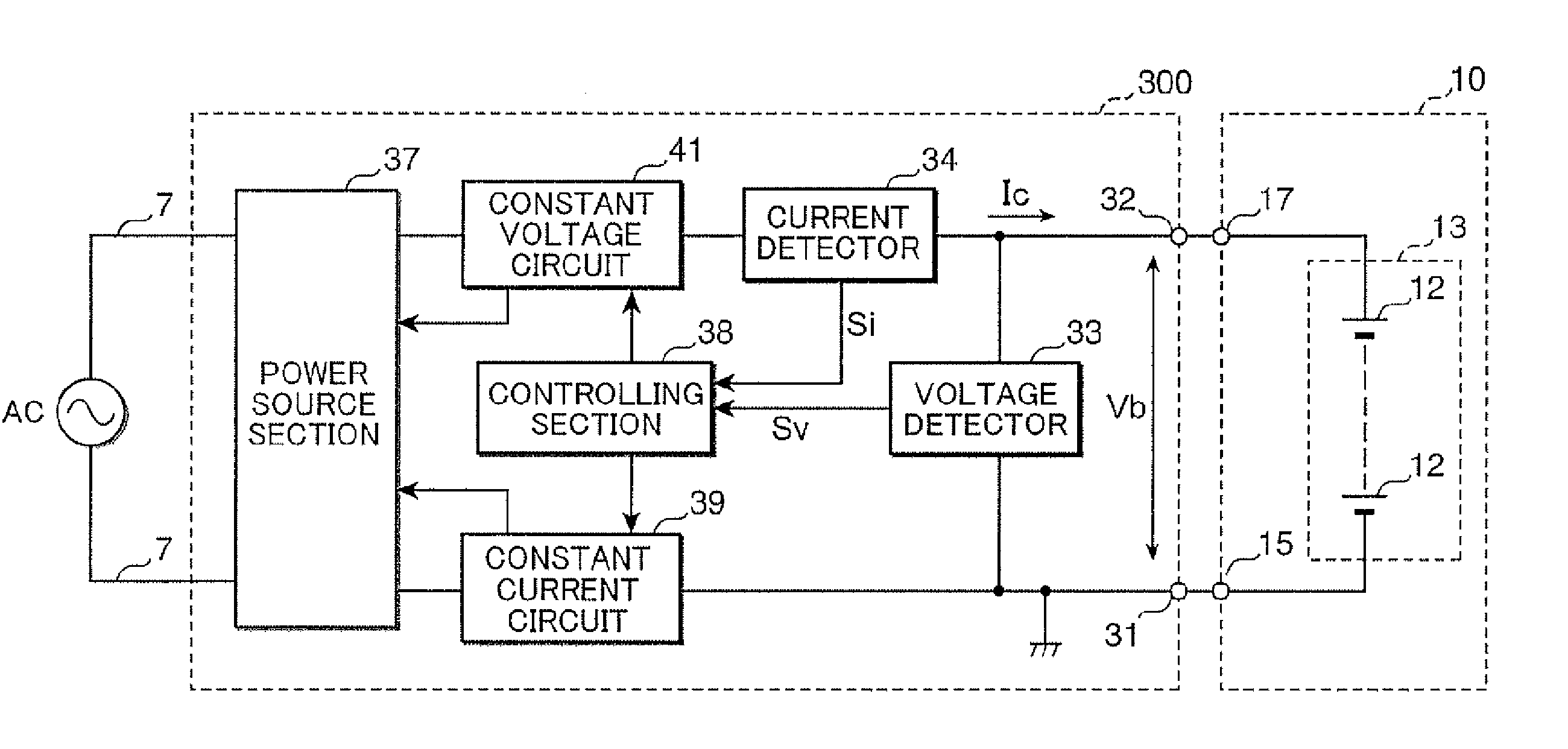
[0059]FIG. 9 is a block diagram showing an example of an arrangement of the charging circuit 300a. The charging circuit 300a shown in FIG. 9 is different from the charging circuit 300 in the first embodiment in that a controlling section 38a executes e.g. a predetermined control program stored in an ROM so that the charging circuit 300a is additionally functioned as a current increase rate setter 381. The construction and the operation of the...


PUM


Abstract

When charging of a secondary battery is started, a power source section for supplying an electric current for charging the secondary battery gradually increases the supply amount of the current. If the charging current has reached a predetermined first threshold current, the power source section is operative to set the supply amount of the current to a predetermined constant current for a constant current charging. If a terminal voltage of the secondary battery has reached a predetermined threshold voltage, the power source section is operative to supply a predetermined voltage for a constant voltage charging to the secondary battery.

Description

BACKGROUND OF THE INVENTION [0001] 1. Field of the Invention [0002] The present invention relates to a charging method, a charging circuit, and a charging device of a secondary battery. [0003] 2. Description of the Related Art [0004] In recent years, there have been widely used various secondary batteries such as lithium ion secondary batteries and nickel hydride secondary batteries, as a drive source for electric equipment such as electric tools and mobile phones. Overcharging such a secondary battery may cause breakage of a battery pack or shorten the life of the secondary battery. In particular, an adverse effect by overcharging is serious in the lithium ion secondary batteries. Overcharge of the secondary battery can be prevented by slowly charging with a less charging current, and by suspending the charging when the voltage of the secondary battery has reached a predetermined value. The less flow of the charging current, however, may increase a charging time. [0005]FIG. 12 is a...

Claims


Application Information

Patent Timeline
Patent Type & Authority Applications(United States)
IPC IPC(8): H02J7/00
CPCH02J7/0073H02J7/008H02J7/041H02J7/0071H02J7/04H02J7/00714H02J7/007182
Inventor OHASHI, TOSHIHARUSAKAUE, MASAAKIITO, MASATOSHI
Owner MATSUSHITA ELECTRIC WORKS LTD
Why Eureka
Try Eureka