Piezoelectric Transducer Signal Processing Circuit

a transducer and signal processing technology, applied in the field of piezoelectric transducer systems, can solve the problems of high impedance operational amplifiers and relatively expensive conventional piezoelectric detector transconductance circuits

Active Publication Date: 2007-05-17
SUREN SYST
View PDF3 Cites 36 Cited by
  • Summary
  • Abstract
  • Description
  • Claims
  • Application Information

AI Technical Summary

Benefits of technology

[0008] In one embodiment, a piezoelectric detector includes a piezoelectric transducer and a transconductance circuit electrically connected to the transducer. The transconductance circuit includes ...

Problems solved by technology

As understood herein, heretofore conventional transconductance circuits for piezoelectric detectors have required relatively expen...

Method used


Image

  • Piezoelectric Transducer Signal Processing Circuit
  • Piezoelectric Transducer Signal Processing Circuit
  • Piezoelectric Transducer Signal Processing Circuit

Examples


Embodiment Construction

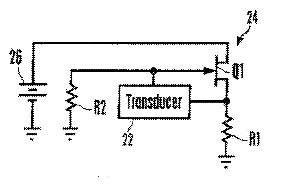
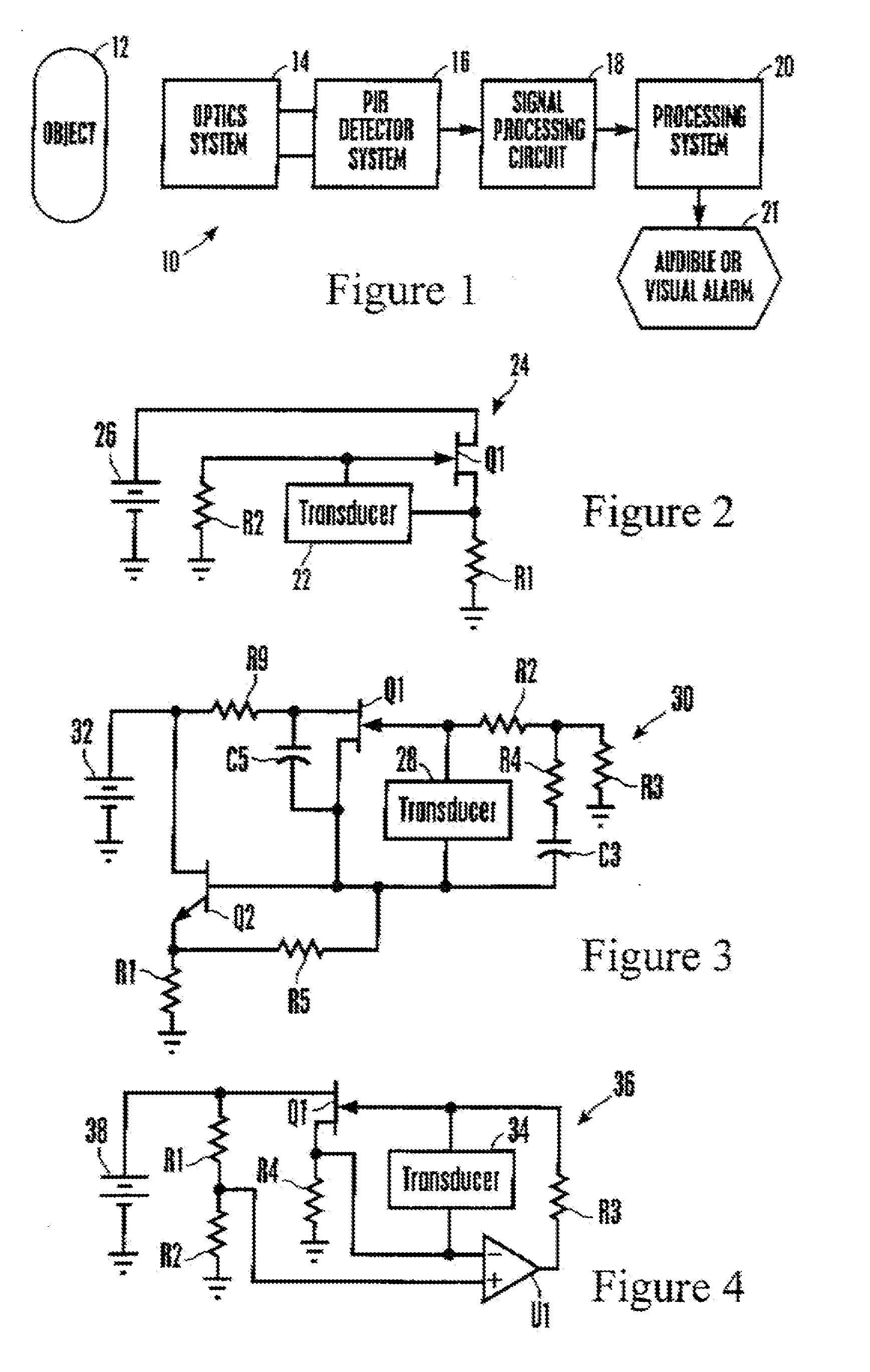
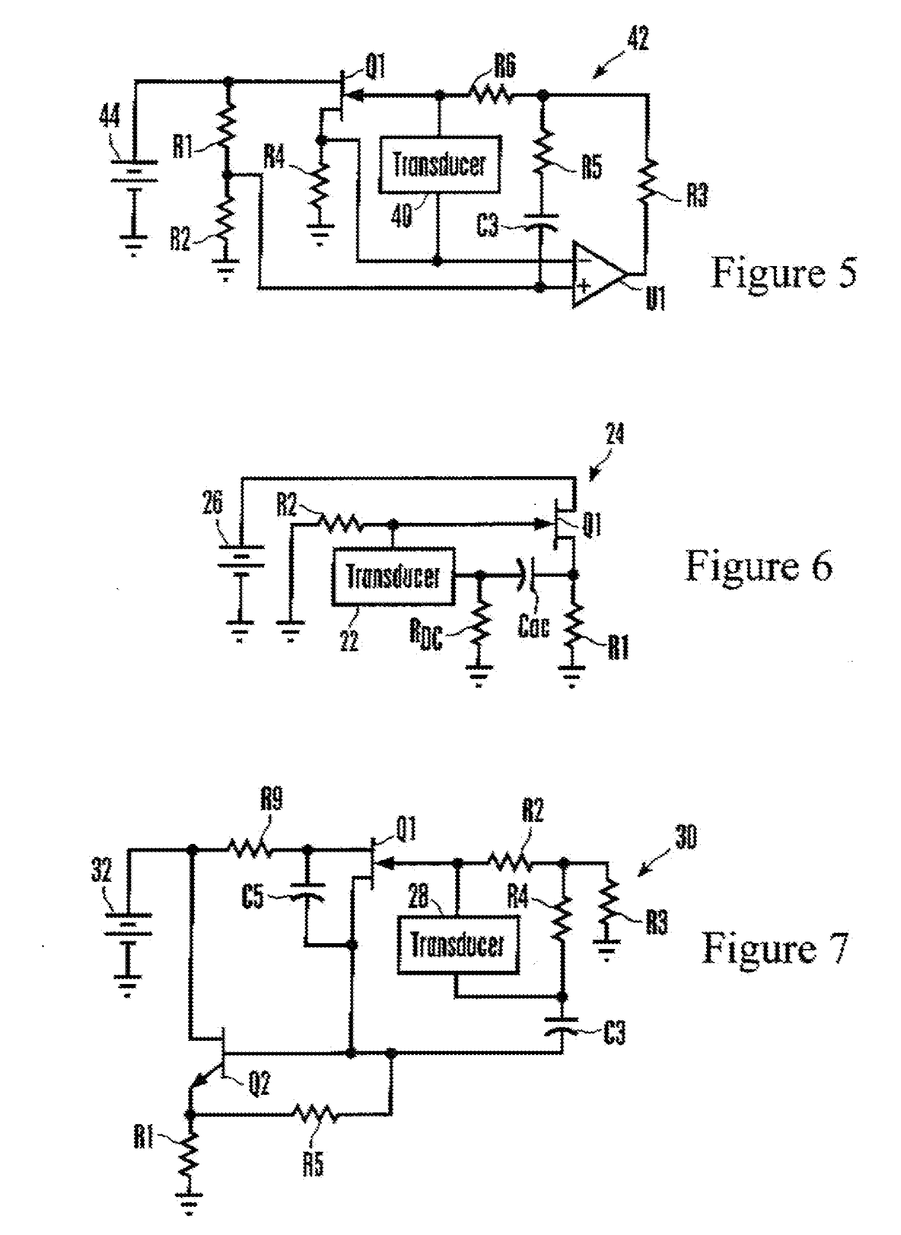
[0044] Certain embodiments as disclosed herein provide for piezoelectric transducer signal processing circuits. For example, one circuit described herein has an input line and a piezoelectric transducer in the input line, an amplifier receiving signals on the input line and generating an output based on the transducer signal, and at least one feedback element through which the output is sent back to the input line.

[0045] After reading this description it will become apparent to one skilled in the art how to implement the invention in various alternative embodiments and alternative applications. However, although various embodiments of the present invention will be described herein, it is understood that these embodiments are presented by way of example only, and not limitation. As such, this detailed description of various alternative embodiments should not be construed to limit the scope or breadth of the present invention as set forth in the appended claims.

[0046] Referring init...


PUM


Abstract

A piezoelectric detector circuit has at least one input line, a piezoelectric transducer in the input line, an amplifier receiving signals on the input line and generating an output, and one or two feedback elements through which the output is sent back to the input line. The circuit may be a discrete time sampled operational amplifier (DTOA) based transconductance or “voltage output mode” circuit. In one embodiment, protection elements are associated with amplifier input lines to establish a reference voltage.

Description

RELATED APPLICATIONS [0001] This is a continuation-in-part of and claims priority from pending U.S. patent application Ser. No. 11 / 298,541, filed Dec. 9, 2005, which is a CIP of pending U.S. patent application Ser. No. 10 / 918,080, filed Aug. 13, 2004, which is a CIP of U.S. patent application Ser. No. 10 / 812,603, filed Mar. 30, 2004, now U.S. Pat. No. 7,042,134, claiming priority in turn from U.S. provisional application Ser. No. 60 / 459,516, filed Mar. 31, 2003, all of which are incorporated herein by reference.FIELD OF THE INVENTION [0002] The present invention relates generally to piezoelectric transducer systems. BACKGROUND OF THE INVENTION [0003] Piezoelectric sensor systems are used in a wide variety of applications. As but one non-limiting example, some security systems detect movement in a monitored space using passive infrared (PIR) motion sensors, which detect changes in far infrared radiation (8-14 micron wavelength) due to temperature differences between an object (e.g. a...

Claims


Application Information

Patent Timeline
IPC IPC(8): H03B5/32
CPCG08B13/191H01L41/042H03F1/34H03F3/181H03F3/347H03F3/45475H03F3/70H03F2203/45528H10N30/802
Inventor MICKO, ERIC SCOTT
Owner SUREN SYST
Why Eureka
Try Eureka