Card cases and wallets with radio frequency shielding

a card case and radio frequency shielding technology, applied in the direction of money bags, burglar alarm mechanical actuation, instruments, etc., can solve the problems of identity and other information theft issues that may become increasingly common, data transmitted through the air can be intercepted and read by unauthorized devices and individuals, and achieve the effect of improving grip

Inactive Publication Date: 2007-05-17
EDENFIELD BENJAMIN W
View PDF10 Cites 79 Cited by
  • Summary
  • Abstract
  • Description
  • Claims
  • Application Information

AI Technical Summary

Benefits of technology

[0021] In another embodiment, an RFID shielding apparatus includes a bottom half of an enclosure, a top half of an enclosure, an overlapping connection between the bottom half and the top half, an enclosure space between the bottom half and the top half for holding enclosed RFID devices, shielding on inner surfaces or within the bottom half and the top half for completely attenuating wavelengths associated with the enclosed RFID devices, a shielded access covering an access opening in the top half, lugs on an underside of the top half for sliding the shielded access from an initial position to an open position and back to an initial position. The shielding on the bottom half and the top half and on the access opening and top overlap. The device may also include ridges on the shielded access for improving grip.

Problems solved by technology

However, there are several drawbacks to RFID technology as it currently exists.
Specifically, these drawbacks include ensuring that only authorized readers or personnel have access to information.
Identity and other information theft issues may become increasingly common as contactless RFID technology is integrated into important personal documents, such as credit cards, passports and other documents.
Furthermore, data transmitted through the air can be intercepted and read by unauthorized devices and individuals.
It is difficult to unwrap and reuse foil regularly.
It is also difficult to place a foil wrapped credit card in a wallet.
The appearance of a foil wrapped credit card or passport is not visually appealing and may arouse suspicion from customs officials or produce an alarm in a metal detector.
Furthermore, if the foil is not wrapped well, RF / EM signals may reach the contactless RFID device, defeating the purpose of wrapping the RFID device.
However, Mylar bags still carry the risk of insufficient closure or potential for opening during transport.
Mylar bags are also susceptible to being cut, thus eliminating any protection.
Other RFID shielding solutions are not readily portable and may not be useful for contactless RFID technology in personal devices.

Method used


Image

  • Card cases and wallets with radio frequency shielding
  • Card cases and wallets with radio frequency shielding
  • Card cases and wallets with radio frequency shielding

Examples


first embodiment

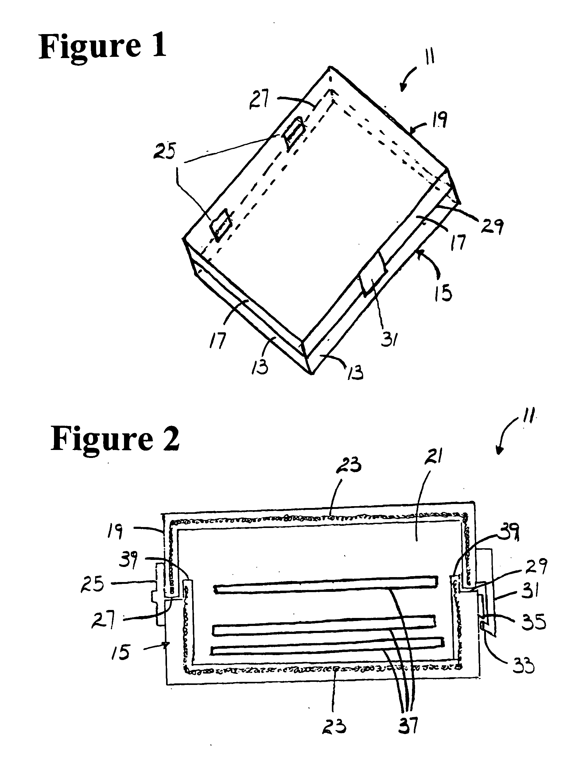
[0038]FIGS. 1-3 show a portable enclosure 11. The device 11 has a four-walled 13 flat base 15 and a four-walled 17 flat cover 19. The flat base 15 and the flat cover 19 fit together to create an enclosed space 21. Shielding 23 is located on an inner surface of or within the flat base 15 and the flat cover 19. The shielding 23 is preferably, but not limited to, a metal wire knit or weave, solid metal, particulate matter, knit fabric or other material that may work by just weakening or attenuating the wavelengths associated with enclosed RFID devices. The shielding 23 creates a complete Faraday cage when closed. Base walls 13 overlap 39 with top walls 17. The base 15 and the cover 19 are hinged together with one or more hinges 25 along corresponding edges 27 of the base 15 and the cover 19. The opposite edges 29 of the base 15 and the cover 19 holds a slightly flexible latch 31 that snaps into engagement when closed. The latch 31 has a protrusion 33 that snaps over a catch 35. Unfaste...

second embodiment

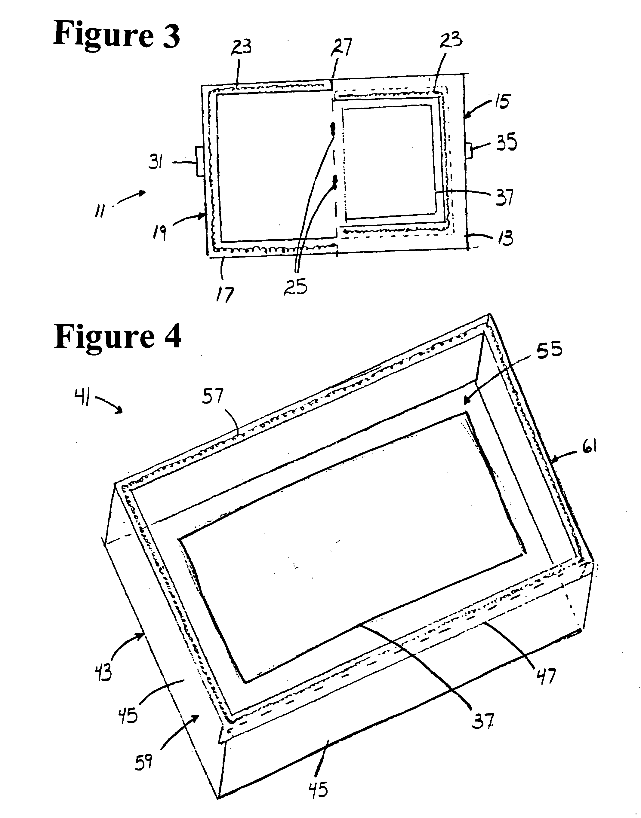
[0039]FIGS. 4-6 show a portable enclosure 41. A base 43 has four walls 45 with outwardly re-entrant shielded edges 47. A top 49 has complementary inwardly re-entrant shielded edges 51. The top 49 is slid along the base 43 to retrieve or place devices 37 with embedded RFID within an enclosed space 55. The top 49 may be slid either towards a front 59 or a rear 61 of the base 43 to open the device 41. Shielding 57 is located on an inner surface or throughout the top 49 and the base 43. When the device 41 is closed a complete Faraday cage is created and no RFID information is transmitted outside the device 41.

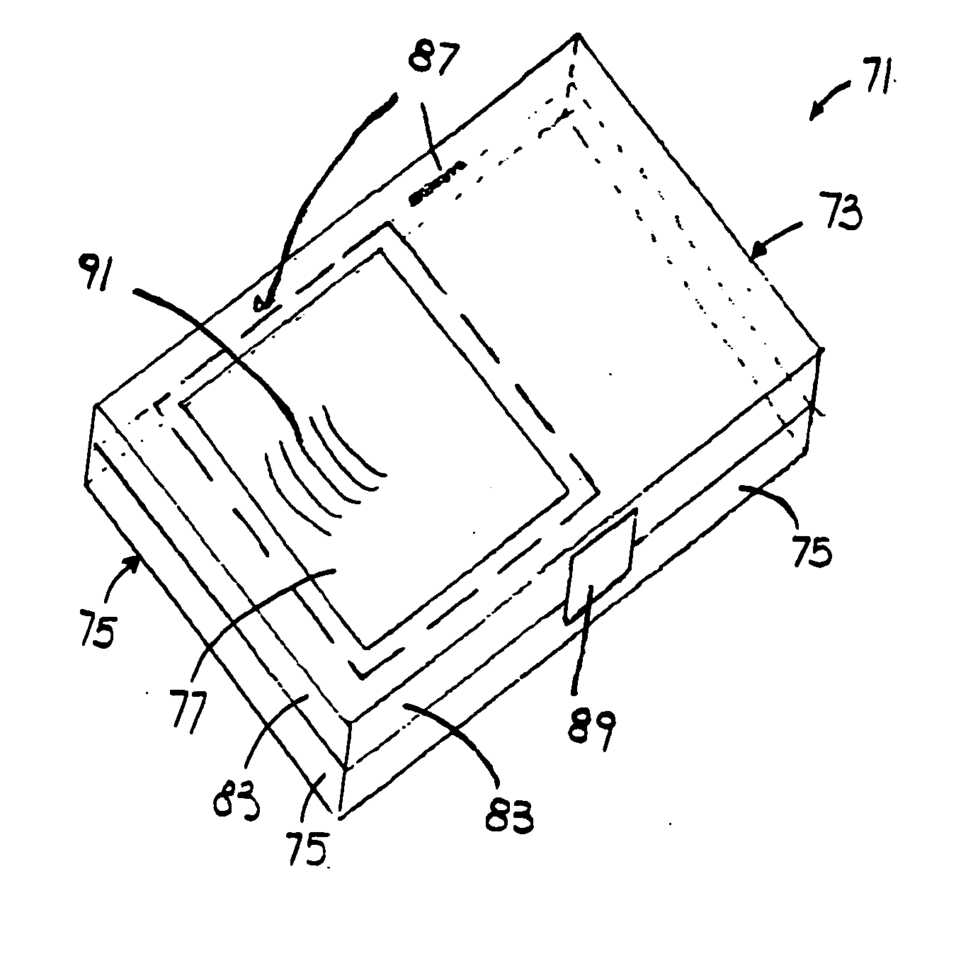
[0040]FIGS. 7-8 show a third embodiment of a portable enclosure 71. A shielded top 73 fits onto a shielded base 75. A shielded access 77 slides along lugs 79 under the top 73 to open an access opening 81. The shielded access 77 is slid back to an initial position to close the device 71. The access opening 81 allows omni directional reading of an RFID tag. Shielded side walls 83 of ...


PUM


Abstract

A portable enclosure has a hinged or slide opening capable of containing several RFID tags embedded in other devices. The present invention provides two layer portable enclosures. The inner layer is a protective layer that keeps signals from hitting the RFID tags. The outer layer is a physical barrier against the elements and serves a decorative function. The inner layer metal is preferably, but not limited to, copper, silver, aluminum, tin or any other metal capable of attenuating completely the wavelength necessary to reach and activate the embedded RFID tag. The metal may be in a weave, solid or any other structure capable of the necessary shielding. The outer layer is made of materials capable of withstanding use, weather, and the surrounding environment. The inner layer may be embedded within the outer layer. A wallet is made of shielding material with flaps surrounding the devices with embedded RFID.

Description

FIELD OF THE INVENTION [0001] The present invention relates to the field of radio frequency electromagnetic signal shielding for contactless cards. BACKGROUND OF THE INVENTION [0002] Contactless cards are widely used. An estimated distribution adds more than one billion cards per year. Contactless cards interact with and receive power from contactless readers by fine wire or printed antennas embedded in the cards. The antennas are connected to micro circuit chips and memories within the cards. Contactless payment devices are usually read within short distances of a few inches. Contactless radio frequency identification cards are designed to be read at larger distances. [0003] Radio frequency electromagnetic signal technology uses wireless communication of signals in radio frequency bands to power and transmit data from contactless tags to contactless cards and readers. A tag or chips and an antenna are attached to or embedded in an object to be identified. A contactless reader power...

Claims


Application Information

Patent Timeline
Patent Type & Authority Applications(United States)
IPC IPC(8): G08B13/14H01Q1/52
CPCA45C1/06A45C11/182A45C2001/065A45C2011/186G06K19/005G06K19/07327G06K19/077
Inventor EDENFIELD, BENJAMIN W.
Owner EDENFIELD BENJAMIN W
Why Eureka
Try Eureka