Resonant frequency tunable antenna apparatus

a tunable antenna and frequency technology, applied in the direction of resonant antennas, radiating elements structural forms, elongated active elements feed, etc., can solve the problems of interference and noise in the antenna, low frequency bandwidth of the broadcasting antenna, and difficult process, so as to enhance the antenna. , the effect of simplifying the signal lin

Inactive Publication Date: 2007-05-17
SAMSUNG ELECTRO MECHANICS CO LTD
View PDF5 Cites 24 Cited by
  • Summary
  • Abstract
  • Description
  • Claims
  • Application Information

AI Technical Summary

Benefits of technology

[0009] The present invention has been made to solve the foregoing problems of the prior art and therefore an object according to certain embodiments of the present invention is to provide a resonant frequency tunable antenna apparatus which turns on / off a switching device in response to a DC voltage applied to a radiation pattern to simplify a signal line, and is designed in an adequate arrangement to enhance antenna properties.

Problems solved by technology

But, in general, broadcasting antennas are low in frequency and wide in frequency bandwidth compared to wireless LANs or short-range wireless telecommunications.
But such a conventional switching method requires separate signal lines for switching on / off to be disposed in a narrow antenna space, which accordingly is a difficult process.
In addition, the signal lines for switching on / off cause interruption and noises in the antenna.

Method used


Image

  • Resonant frequency tunable antenna apparatus
  • Resonant frequency tunable antenna apparatus
  • Resonant frequency tunable antenna apparatus

Examples


Embodiment Construction

[0025] Preferred embodiments of the present invention will now be described in detail with reference to the accompanying drawings.

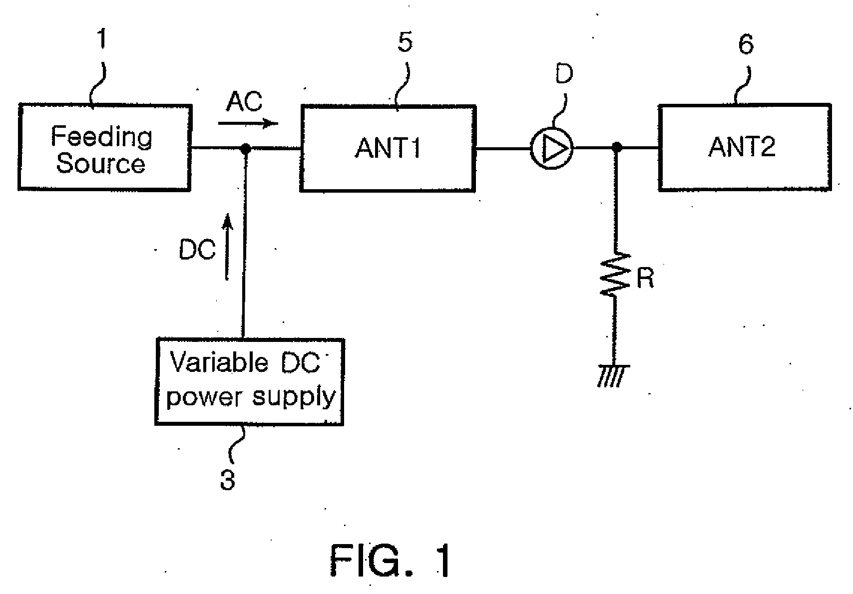
[0026]FIG. 1 is a basic conceptual view illustrating an antenna apparatus according to the invention.

[0027] Referring to FIG. 1, the antenna apparatus of the invention includes at least two antennas ANT1 and ANT2. The first antenna ANT1, as a radiation component, has an electrical resonant length corresponding to a first resonant frequency. Meanwhile, the second antenna ANT2, as a tuning radiation component, is combined with the first antenna ANT1 to provide a second resonant frequency, lower than the first resonant frequency. The first and second antennas 5 and 6 are connected with each other by a diode D, which is a switching device.

[0028] According to the invention, the diode is not connected to a separate driving signal line. However, the first antenna 5 is connected to a feeding source and a variable driving power supply 3, thereby receiving both ...


PUM


Abstract

In a tunable antenna apparatus, a dielectric block is mounted on a printed circuit board. A radiation pattern has a feeding part formed on the dielectric block and connected commonly to a feeding source and a variable DC power. Also, a connecting pattern extends from the radiation pattern onto the printed circuit board. In addition, at least one tuning pattern is formed on the printed circuit board and connected in series to the connecting pattern via at least one switching device.

Description

CLAIM OF PRIORITY [0001] This application claims the benefit of Korean Patent Application No. 2005-71583 filed on Aug. 5, 2005, in the Korean Intellectual Property Office, the disclosure of which is incorporated herein by reference. BACKGROUND OF THE INVENTION [0002] 1. Field of the Invention [0003] The present invention relates to an antenna, and more particularly to an antenna apparatus which adjusts an electrical resonant length in a wide frequency bandwidth via a switching device to vary a resonant frequency into a desired available frequency band. [0004] 2. Description of the Related Art [0005] With recent advancement in a mobile multimedia broadcasting technology, there has arisen a need to develop terrestrial broadcasting antennas and satellite broadcasting antennas suitable for a mobile telecommunication terminal. [0006] But, in general, broadcasting antennas are low in frequency and wide in frequency bandwidth compared to wireless LANs or short-range wireless telecommunicat...

Claims


Application Information

Patent Timeline
Patent Type & Authority Applications(United States)
IPC IPC(8): H01Q1/24
CPCH01Q1/243H01Q1/38H01Q9/0442H01Q9/42
Inventor PARK, IL HWANKIM, HYUN HAKLEE, YONG BUMKIM, JONG LAE
Owner SAMSUNG ELECTRO MECHANICS CO LTD
Why Eureka
Try Eureka