Matrix architecture for KVM extenders

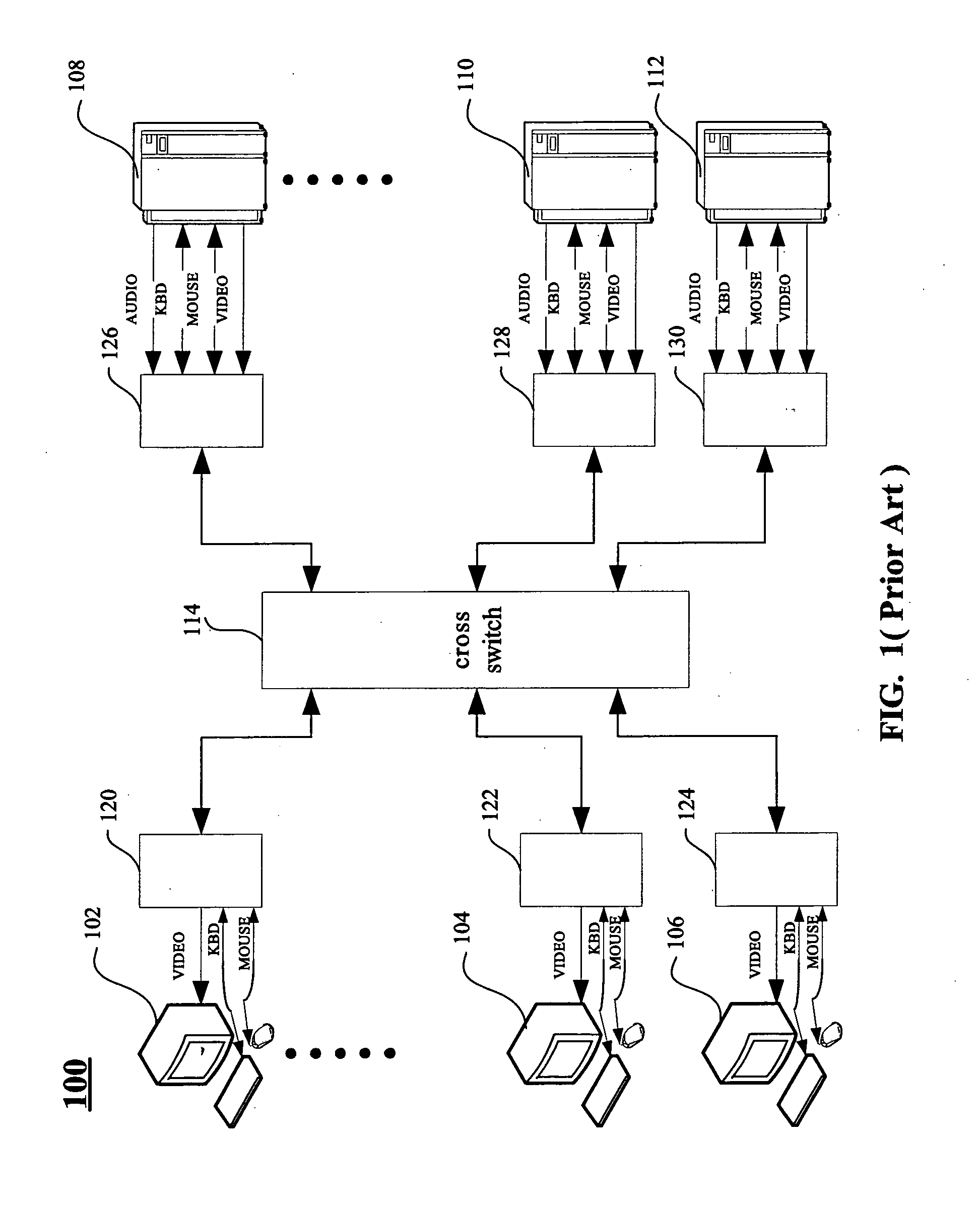
a technology of matrix architecture and extender, applied in the field of matrix architecture, can solve the problems of inability to work as far as practicable without cross switch, complex and costly cross switch 114, and each user operating at the remote console device takes a risk equally, so as to prevent the decay of signal transmission, simplify the structure, and extend the distance between the console terminal and the computer.

Active Publication Date: 2007-05-17
ATEN INT CO
View PDF23 Cites 14 Cited by
  • Summary
  • Abstract
  • Description
  • Claims
  • Application Information

AI Technical Summary

Benefits of technology

[0012] Specifically, the broadcasters, such as hubs, broadcast the keyboard, video and mouse data packets in the standard of Ethernet. As a result, the present matrix architecture can extend the distance between the console terminals and computers by the added one or more packet transceivers as the relay to prevent the decay of the signal transmission. Although, the well-known 5-4-3 rule must apply with only regards to hubs as described after for limiting the size of the collision domain not to be too large for well network. “There may be a maximum of 5 segments between two hosts in a network, and there may be at most 4 hubs between these hosts and finally there may only be users on 3 of the segments”. Such restriction means: the numbers of hub that we can arrange between any of the console terminals and any of the computers cannot exceed 4. However, we can combine the any kind of packet transceiver, such as a router, a bridge or a switching hub to satisfy the rule of 5-4-3 rule to overcome the rule's limitation. Theoretically, there will be no limitation for extending the distance therebetween as a result. Besides the merit above, with an appropriate wiring arrangement for the broadcasters in the

Problems solved by technology

Furthermore, the cross switch cannot work as far as what it's required practically without the cooperation of the conditioning circuits (120, 122, 124, 126, 128, 130).
However, the cross switch 114 is complicated and costly.
Each of the users who are operating at the remote console devices takes a risk equally.
Un

Method used


Image

  • Matrix architecture for KVM extenders
  • Matrix architecture for KVM extenders
  • Matrix architecture for KVM extenders

Examples


first embodiment

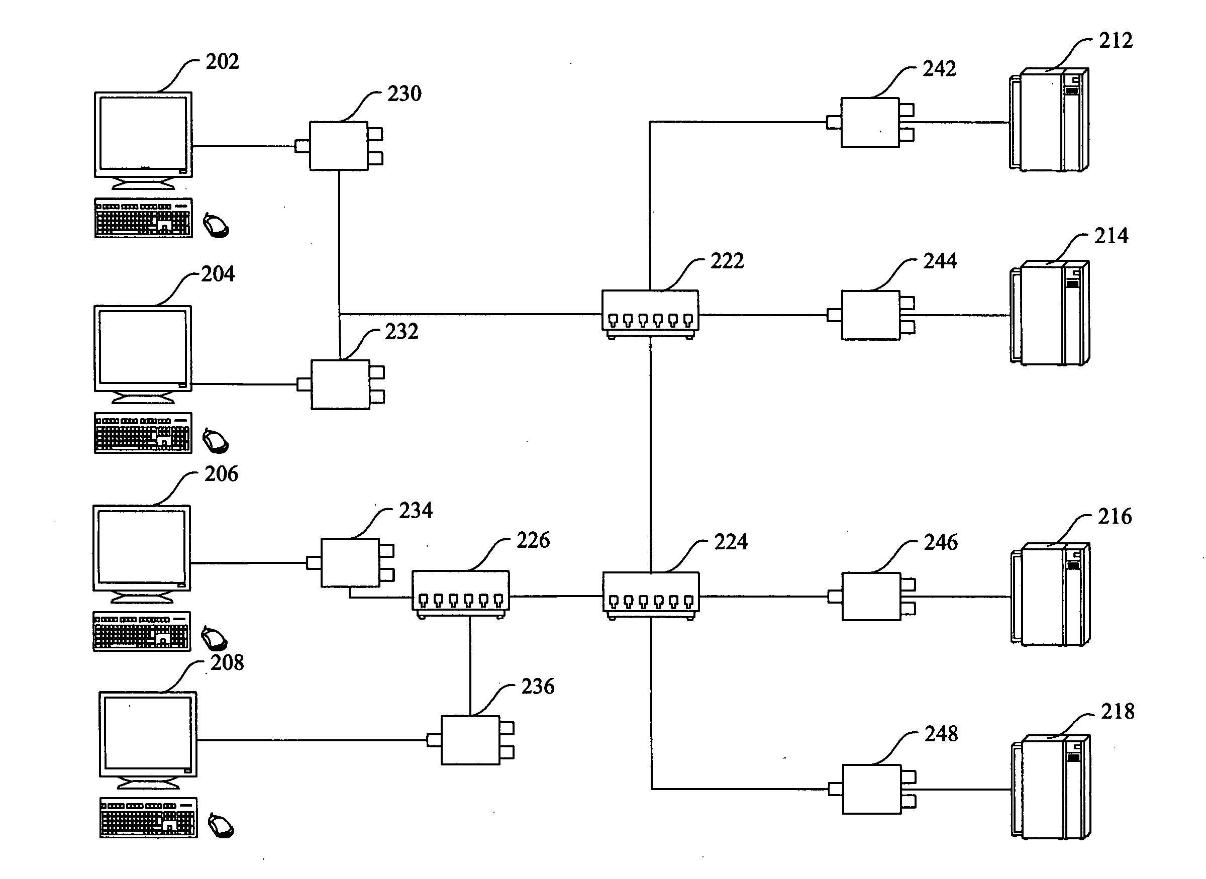
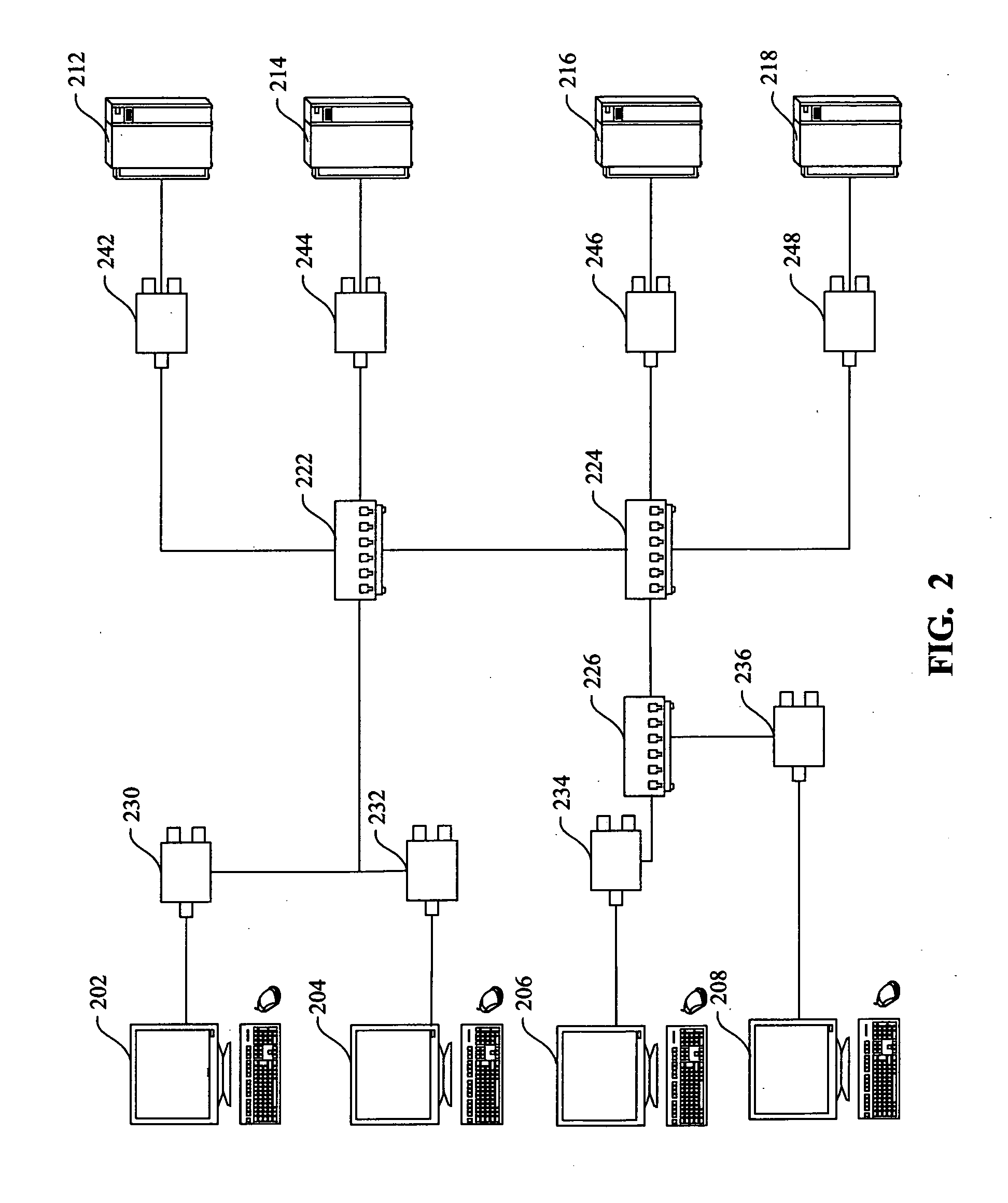
[0022] Please referring to FIG. 2, which shows the matrix architecture for KVM extenders to broadcast keyboard-video-mouse data packets via broadcasters among the console terminals and computers of the present invention. It extends the distance and the simple components inside the first and second extender and avoids that the “whole network” gets down, following that the matrix KVM switch gets crashed in case of using only one cross switch for transmitting signals, since there is only one route between each of the console terminals and each of the computers. The purpose of one or more routes between each console terminal and each computer is to erase the probability of the whole network's getting crashed caused by the cross switch for transmitting signals centrally. With the appropriate wiring arrangement for the broadcasters in the matrix architecture, the object can be achieved. First, the console terminals (202, 204, 206, 208) and the computers (212, 214, 216, 218) own the uniqu...

second embodiment

[0027] Please further referring to the FIG. 3, which is the matrix architecture for KVM extenders to broadcast keyboard-video-mouse data packets via broadcasters among the console terminals and computers according to the present invention. For example, the user is controlling the computer 212 at the console terminal 202 through the first extender 230 coupled to the console terminal 212 and the second extender 242 coupled to the computer 202. Normally, the route is hub 304-hub 310. If hub 304 crashed, the route changes to another route, such as hub 306-hub 302-hub 310. If hub 310 crashed, the route changes to another route, such as hub 304-hub 302-hub 308. If hub 304 and hub 310 crashed, the route changes to another route, such as hub 306-hub 308. Here is the illustration of the console terminal 202 goes with the computer 212. Various combinations of the console terminals and computers can achieve the same result.

third embodiment

[0028] Please referring to FIG. 4 which shows third embodiment of the matrix architecture for KVM extenders to broadcast keyboard-video-mouse data packets via broadcasters among the console terminals and computers according to the present invention and FIG. 3. Such as the users are controlling either the computer (212, 214) at the console terminals 202 or 204 through the first extenders (230, 232) coupled to console terminals (212, 214), respectively and the second extenders (242, 244) coupled to the computers (212, 214), respectively. There will be at least two routes provided to broadcast the keyboard, mouse data packets from each of the console terminals to each of the computers in the matrix architecture or broadcast the video data packets in reverse order. As a result, the crash of the network caused by the failure of the only one cross switch transmitting signals can be avoided with such appropriate wiring arrangement for the hubs in the matrix architecture. Meanwhile, the pre...


PUM


Abstract

A matrix architecture for KVM extenders connecting a plurality of console terminals and a plurality of computers. The matrix architecture for KVM extenders includes a plurality of first extenders and a plurality of second extenders. The first extenders transform keyboard, mouse analog signals into keyboard, mouse data packets and transform video data packets into video signals for console terminals. The second extenders transform video signals into video data packets and transform keyboard, mouse data packets into keyboard, mouse analog signals. The broadcasters broadcast keyboard, video, mouse data packets, each having a source address and a target address to couple computers to console terminals by broadcasting video data packets from second extenders to first extenders and to couple console terminals to computers by broadcasting keyboard, mouse data packets from first extenders to second extenders.

Description

FIELD OF THE INVENTION [0001] The present invention generally relates to a matrix architecture and more particularly to a matrix architecture for KVM extenders interconnecting among a plurality of consoles and a plurality of computers. BACKGROUND OF THE INVENTION [0002] The keyboard-video-mouse (KVM) switch interconnecting a plurality of console devices and a plurality of computers with conditioning circuits coupled to the corresponding console devices and computers is a so-called matrix KVM switch. It is a solution to the access of computers through the matrix cross switch to remotely control the selected computers at the console device for multi-users. Referring to FIG. 1, a traditional matrix cross switch for interconnecting a plurality of remote console devices and computers is shown. The prior arts related with such traditional cross switch has been disclosed in U.S. Pat. No. 5,721,842, U.S. Pat. No. 5,884,096, U.S. Pat. No. 5,937,176, U.S. Pat. No. 6,345,323 and U.S. Pat. No. ...

Claims


Application Information

Patent Timeline
IPC IPC(8): G09G5/08
CPCG09G5/006G09G2370/24
Inventor SIM, KHENG-CHUANLIU, WEI-HSIENHSIEH, CHIH-TAO
Owner ATEN INT CO
Why Eureka
Try Eureka