Power optimized collocated motion estimation method

a motion estimation and power optimization technology, applied in the field of power optimization of collocated motion estimation methods, can solve the problems of inoptimized motion estimation methods, large power consumption, and most memory transfers, and achieve the effects of reducing memory transfer, reducing energy dissipation of a corresponding video encoding circuit, and increasing the reliability of said circui

Inactive Publication Date: 2007-05-17
ENTROPIC COMM INC
View PDF4 Cites 10 Cited by
  • Summary
  • Abstract
  • Description
  • Claims
  • Application Information

AI Technical Summary

Benefits of technology

[0014] On the one hand, the motion estimation method in accordance with the invention uses only a restricted set of data samples, which is a reference block having a same position in the reference frame as the current block has in the current frame. Said reference block is also called the collocated block. Thanks to the use of said reduced set of data samples, the motion estimation method according to the invention is an efficient way to reduce memory transfer at the encoder and at the decoder. Moreover, reducing the energy dissipation of a corresponding video encoding circuit increases the reliability of said circuit and allows a significant attenuation of the cooling effort. Therefore production costs are greatly lowered.
[0015] On the other hand, said motion estimation method is adapted to determine a motion vector between the first reference portion of the reference block and the first current portion of the current block, i.e. by only taking into account portions of said current and reference blocks which are similar. Said motion vector can vary from (−N+1,−N+1) to (N−1,N−1) if the reference block comprises N×N data samples. In addition, the motion estimation method is adapted to predict missing data samples, i.e. the data samples that belong to the second reference portion of the virtual block. As we will see in further detail later on, this prediction can be done according to different modes. Thanks to the determination of a motion vector and to the prediction of corresponding missing data samples, the motion estimation method according to the invention is capable of keeping a satisfying visual quality.

Problems solved by technology

In a conventional video encoder, most of the memory transfers and, as a consequence, a large part of the power consumption, come from motion estimation.
However, such a motion estimation method is not optimal, especially in the case of a video encoder embedded in a portable apparatus having limited power.
Some of them propose computational simplifications: such methods are not sufficient anymore.
Disadvantages of these states of the art are that either the motion estimation method reduces the video quality too much, or that it does not achieve a sufficient memory transfer saving.

Method used


Image

  • Power optimized collocated motion estimation method
  • Power optimized collocated motion estimation method
  • Power optimized collocated motion estimation method

Examples


first embodiment

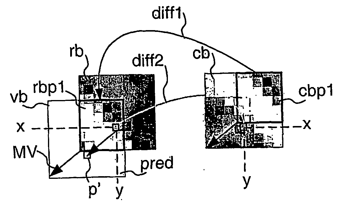
[0053]FIG. 4 illustrates said motion estimation method called collocated prediction. In such an embodiment, a value of a pixel p′ of the second reference portion pred is derived from a value of the pixel corresponding to a translation of the pixel of the second reference portion according to the opposite of the motion vector candidate MV. In other words, the missing pixel p′ is predicted on the basis of the pixel rb(x,y) collocated to the current pixel cb(x,y) as follows:

pred(rb,cb(x,y))=rb(x,y)−cb(x,y).

[0054] It is to be noted in FIGS. 4 to 6 that the arrow diff1 represents the computation of the first difference between pixels of the first reference portion rbp1 and corresponding pixels of the first current portion cbp1 and that the arrow diff2 represents the computing of the second difference.

second embodiment

[0055]FIG. 5 illustrates the motion estimation method called edge prediction. In such an embodiment, a value of a pixel of the second reference portion is predicted on the basis of a first interpolation of a pixel value of the reference block. Said prediction is defined as follows:

pred(rb, cb(x,y))=rb(proj(x),proj(y))−cb(x,y),

[0056] where the proj( ) function is adapted to determine the symmetric p″ of the pixel p′ of the second reference portion pred with reference to a horizontal and / or vertical edge of the reference block and to take the value of said symmetric pixel p″ as the reference value rb(x″,y″), as shown in FIG. 5.

third embodiment

[0057]FIG. 6 illustrates said motion estimation method. It is called spatial interpolation prediction. In this embodiment, a value of a pixel of the second reference portion pred is derived from an interpolation of values of several pixels of the first reference portion. For example, the value of the pixel p′ of the second reference portion is interpolated from the pixels belonging to the reference block rb that are on the same line or column as the pixel p′.

[0058] According to another embodiment of the invention, a single prediction value pred_value is derived from the reference block rb. The corresponding residual error block value is computed as follows:

r(x,y)=cb(x,y)−pred_value

[0059] pred_value is set to the mean of the reference block rb values or the median of said values.

[0060] Still according to another embodiment of the invention, strictly spatial prediction is performed. In that case, the reference block is not used. The prediction value pred_value is an average or a me...


PUM


Abstract

The present invention relates to a method of motion estimation for use in a device adapted to process a sequence of frames, a frame being divided into blocks of data samples. Said motion estimation method comprises a step of computing a residual error block associated with a motion vector candidate (MV) on the basis of a current block (cb) contained in a current frame (CF) and of a reference block (rb) contained in a reference frame (RF), said reference block having a same position in the reference frame as the current block has in the current frame. The motion vector candidate defines a relative position of a virtual block (vb) containing a first reference portion (rbp1) of the reference block with reference to said reference block. The residual error block is then computed from a first difference between data samples of the first reference portion and corresponding data samples of a first current portion (cbp1) of the current block, and a second difference between a prediction of data samples of a second reference portion (pred) of the virtual block, which is complementary to the first reference portion, and data samples of a second current portion (cbp2) of the current block, which is complementary to the first current portion.

Description

FIELD OF THE INVENTION [0001] The present invention relates to a motion estimation method and device adapted to process a sequence of frames, a frame being divided into blocks of data samples. [0002] The present invention relates to a predictive block-based encoding method comprising such a motion estimation method. It also relates to the corresponding encoder. [0003] The present invention finally relates to a computer program product for implementing said motion estimation method. [0004] This invention is particularly relevant for products embedding a digital video encoder such as, for example, home servers, digital video recorders, camcorders, and more particularly mobile phones or personal digital assistants, said apparatus comprising an embedded camera able to acquire and to encode video data before sending it. BACKGROUND OF THE INVENTION [0005] In a conventional video encoder, most of the memory transfers and, as a consequence, a large part of the power consumption, come from m...

Claims


Application Information

Patent Timeline
Patent Type & Authority Applications(United States)
IPC IPC(8): H04N11/02H04B1/66H04N7/26H04N7/50H04N19/593
CPCH04N19/56H04N19/61H04N19/433H04N19/156H04N19/593H04N19/51
Inventor JUNG, JOEL
Owner ENTROPIC COMM INC
Why Eureka
Try Eureka