
Method of acoustic signal reproduction

Inactive Publication Date: 2007-05-17
MITSUBISHI ELECTRIC CORP
View PDF4 Cites 4 Cited by
  • Summary
  • Abstract
  • Description
  • Claims
  • Application Information

AI Technical Summary

Benefits of technology

[0007] Up to now, there have existed filters having a transfer function for canceling crosstalk components arriving from loudspeakers, at the listener's right / left ear, however, such filters have been incapable of properly reducing inter-loudspeaker crosstalk components inside the casing of a mobile terminal. Therefore, when input signals are expected to produce stereophonic effects, mobile terminals have not realized three-dimensional sound image localization. [0005] In a method of acoustic signal reproduction in a mobile terminal with at least two loudspeakers accommodated inside the casing thereof, a crosstalk canceling method of the present invention comprises Processing Step 1 of reducing spatial crosstalk that is generated, with respect to input signals to the loudspeakers, in a space ranging from the loudspeakers to the listener's ears, and Processing Step 2 of reducing crosstalk that is generated between the loudspeakers inside the casing, with respect to Processing-Step-1-processed signals.
[0008] In a method of acoustic signal reproduction in a mobile terminal with at least two loudspeakers accommodated inside a casing the mobile terminal, a crosstalk canceling method of the invention comprises Processing Step 1 of reducing spatial crosstalk that is generated, with respect to the input signals of the loudspeakers, in a space ranging from loudspeakers to the listener's ears, and Processing Step 2 of reducing crosstalk that is generated between the loudspeakers inside the casing, with respect to Processing-Step-1 processed signals, allowing the mobile terminal to realize three-dimensional (3D) sound image localization when the input signals are anticipated to produce the stereophonic effects.

Problems solved by technology

Up to now, there have existed filters having a transfer function for canceling crosstalk components arriving from loudspeakers, at the listener's right / left ear, however, such filters have been incapable of properly reducing inter-loudspeaker crosstalk components inside the casing of a mobile terminal.
Therefore, when input signals are expected to produce stereophonic effects, mobile terminals have not realized three-dimensional sound image localization.

Method used


Image

  • Method of acoustic signal reproduction
  • Method of acoustic signal reproduction
  • Method of acoustic signal reproduction

Examples


embodiment 1

[0018] The inventor's study has revealed that when a speaker-rear air chamber is used in common in order to downsize a casing of a mobile terminal, there occurs a phenomenon in that sound waves being emanated from one loudspeaker acoustically couple with each other inside the casing, and leak out into the other loudspeaker.

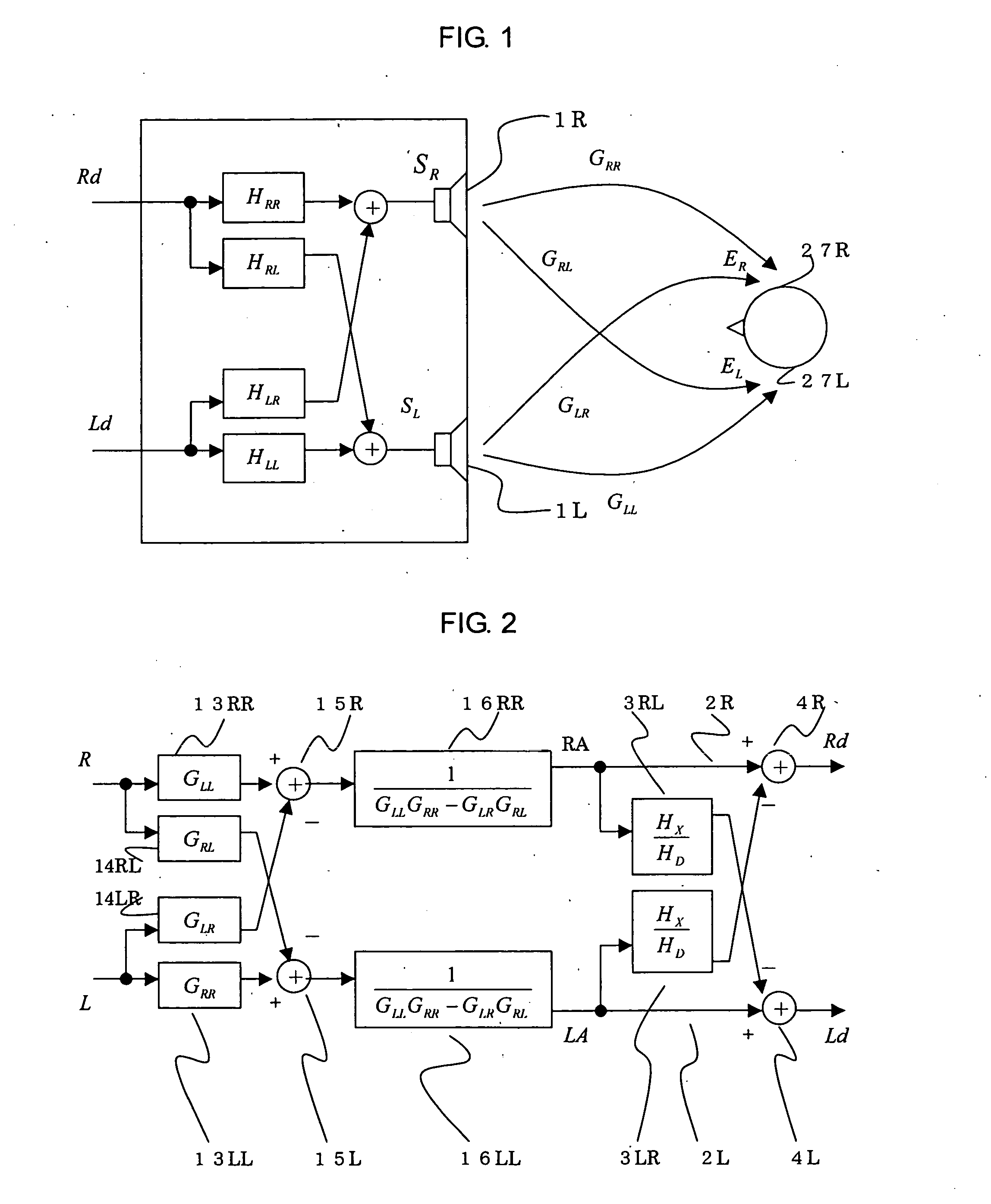
[0019] This acoustic coupling is referred to as in-casing crosstalk. The left part of FIG. 1 is a modeling of this phenomenon. It has also turned out that there has occurred a phenomenon in that sound waves emanated from one loudspeaker, while supposed to arrive at either ear of a listener, couple with each other at the other ear and leak thereinto. This acoustic coupling is referred to as spatial crosstalk. The right part of FIG. 1 is a modeling of this phenomenon.

[0020] A first loudspeaker 1R (one loudspeaker) and a second loudspeaker 1L (the other loudspeaker) each illustrated in FIG. 1 are housed inside a mobile terminal, not shown, and the speaker-rear air ...

embodiment 2

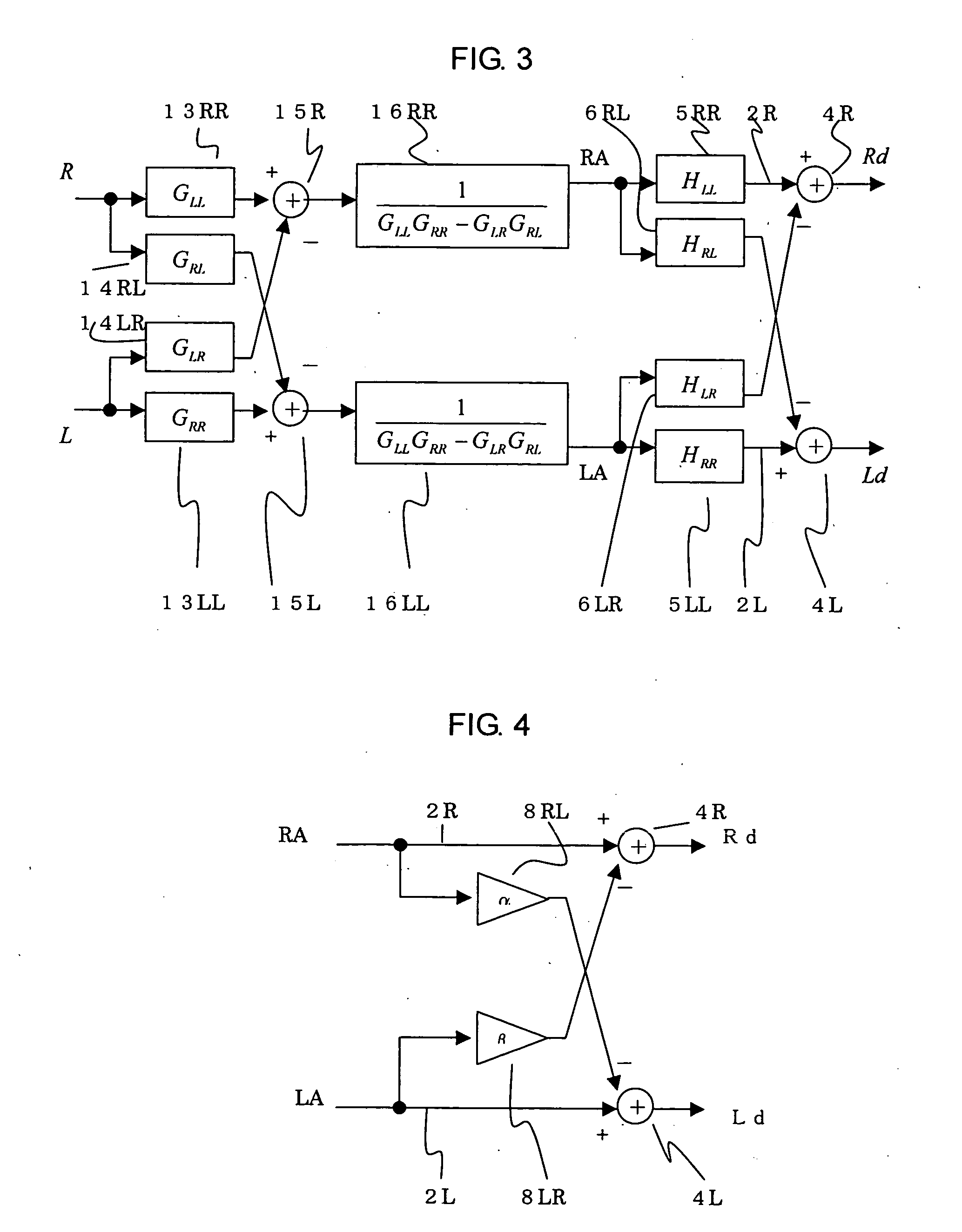
[0039] While in Embodiment 1 of the invention, a first in-casing processing means 3LR and a second in-casing processing means 3RL are used as the processing step for reducing in-casing crosstalk, in Embodiment 2 of the invention, a case will be explained in which a first in-casing processing means 5RR, a second in-casing processing means 5LL, a first crossover processing means 6LR, and a second crossover processing means 6RL, are used. Note that since reproduction of the in-casing crosstalk is similar to that of Embodiment 1 of the invention in FIG. 1, the description will be omitted herein. Furthermore, since reproduction of the spatial crosstalk is also similar to that of Embodiment 1 of the invention in FIG. 1, the description will be omitted herein. Moreover, since the spatial crosstalk processing means is the same as the right portion in FIG. 2, the description will be omitted herein.

[0040]FIG. 3 is a general diagram illustrating an acoustic signal reproduction circuit for use...

embodiment 3

[0049] Although in Embodiment 1 of the invention, the first in-casing processing means3LR and the second in-casing processing means 3RL have been used as the processing step of reducing in-casing crosstalk, in Embodiment 1 of the invention a case is explained in which a first in-casing multiplication processing means 8LR, a second in-casing multiplication processing means 8RL, as will be hereinafter described, are used.

[0050] Note that since the reproduction of the in-casing crosstalk is similar to that as shown in FIG. 1 in Embodiment 1 of the invention, the description will be omitted herein. Furthermore, since the reproduction of the spatial crosstalk is also similar to that as shown in FIG. 1 of Embodiment 1, the description will be omitted herein. Moreover, since the spatial crosstalk processing is the same as the left part of FIG. 2, the description will be omitted herein.

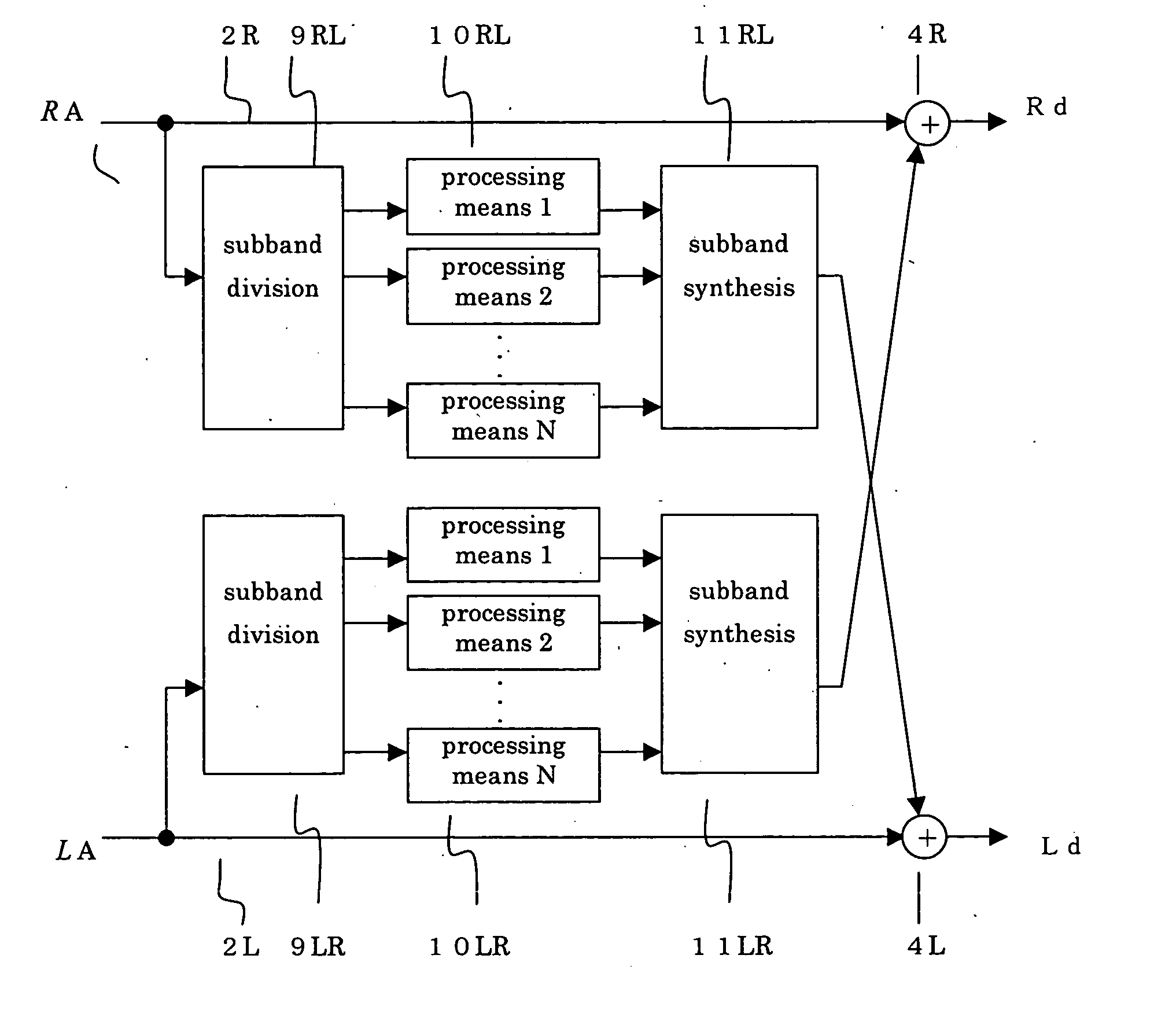
[0051]FIG. 4 is a general diagram illustrating an acoustic signal reproduction circuit for use in a mobi...


PUM


Abstract

Up to now, there have existed filters having a transfer function for canceling crosstalk components arriving from loudspeakers, at the listener's right / left ear, however, such filters have been incapable of properly reducing the inter-loudspeaker crosstalk components inside the casing of a mobile terminal. Therefore, when input signals are expected to produce stereophonic effects, three-dimensional sound image localization has not been realized in mobile terminals. In a method of acoustic signal reproduction in a mobile terminal with at least two loudspeakers accommodated inside the casing of the terminal, a crosstalk canceling method relating to the present invention comprises Processing Step 1 for reducing spatial crosstalk that is generated with respect to the input signals to the loudspeakers, in a space ranging from the loudspeaker to the listener's ears, and Processing Step 2 for reducing crosstalk that is generated between the loudspeakers inside the casing, with respect to Processing-Step-1-processed signals.

Description

TECHNICAL FIELD [0001] The present invention relates to methods of acoustic signal reproduction, for reducing crosstalk that is generated at the time of using a mobile terminal. BACKGROUND ART [0002] Conventional crosstalk cancellers are characterized by a filter having a transfer function for canceling crosstalk components arriving at the listener's right / left ear, in regard to the transfer function through which virtual acoustic image corresponding to input signals is considered to arrive at the listener's right / left ear. [0003] Patent Document 1 [0004] Japanese Laid-Open Patent Publication H09-327099 (pages 1 and 2) [0005] Patent Document 2 [0006] Japanese Laid-Open Patent Publication 2002-111817 (pages 1, 2, 9 and 10) DISCLOSURE OF THE INVENTION [0007] Up to now, there have existed filters having a transfer function for canceling crosstalk components arriving from loudspeakers, at the listener's right / left ear, however, such filters have been incapable of properly reducing inter...

Claims


Application Information

Patent Timeline
IPC IPC(8): H04R5/00H04R1/20H04S1/00H04S5/02
CPCH04S1/002
Inventor KIMURA, MASARUMATSUOKA, BUNKEI
Owner MITSUBISHI ELECTRIC CORP
Learn More