
Method and system for generating polygonal boundary definitions for image objects

a polygonal boundary and definition technology, applied in image analysis, image enhancement, instruments, etc., can solve the problems of inefficiency, inability to define manually, and severely limit the degree to which such 2d image element hot linking has been used, so as to reduce the size of the boundary pixel list

Active Publication Date: 2007-05-17
GENERAL ELECTRIC CO
View PDF5 Cites 7 Cited by
  • Summary
  • Abstract
  • Description
  • Claims
  • Application Information

AI Technical Summary

Benefits of technology

[0006] The ultimate list of boundary pixels may then be reduced. Where three or more pixels lie in a line, for example, intermediate pixels may be deleted from the list to reduce the size of the boundary pixel list. Similarly, where boundary pixels

Problems solved by technology

A difficulty encountered in segmenting portions of an image for such linking, and for other purposes, involves the process of identification of a polygon that describes the item boundaries.
Conventionally, such boundaries have been defined manually in an extremely time-consuming process.
The resulting cost of boundary identification for such tagging has severely limited the degree to which such 2D image element hot linking has been used.
However, their complexity and relative computational inefficiency also makes them limited in their use.

Method used


Image

  • Method and system for generating polygonal boundary definitions for image objects
  • Method and system for generating polygonal boundary definitions for image objects
  • Method and system for generating polygonal boundary definitions for image objects

Examples


Embodiment Construction

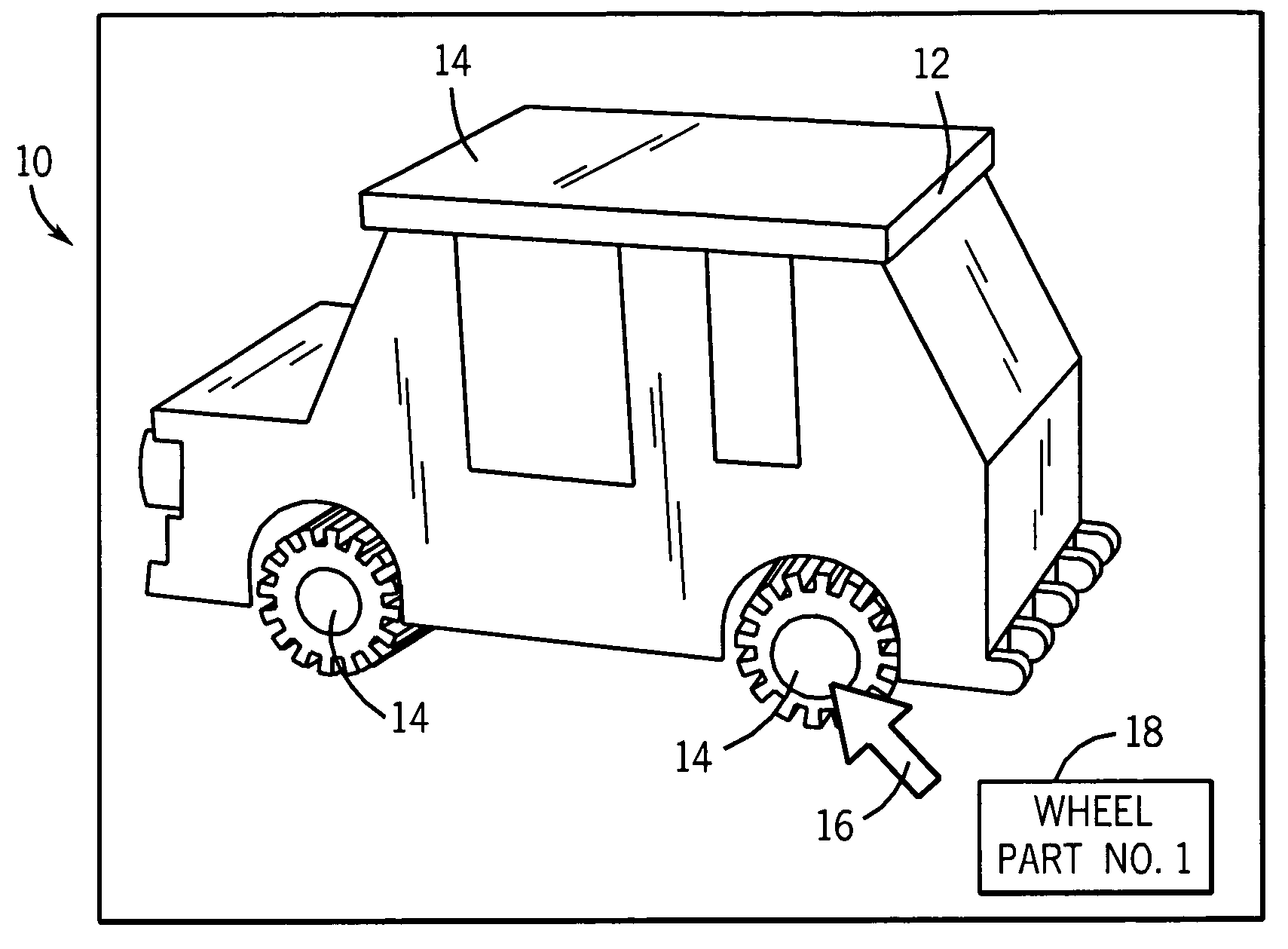
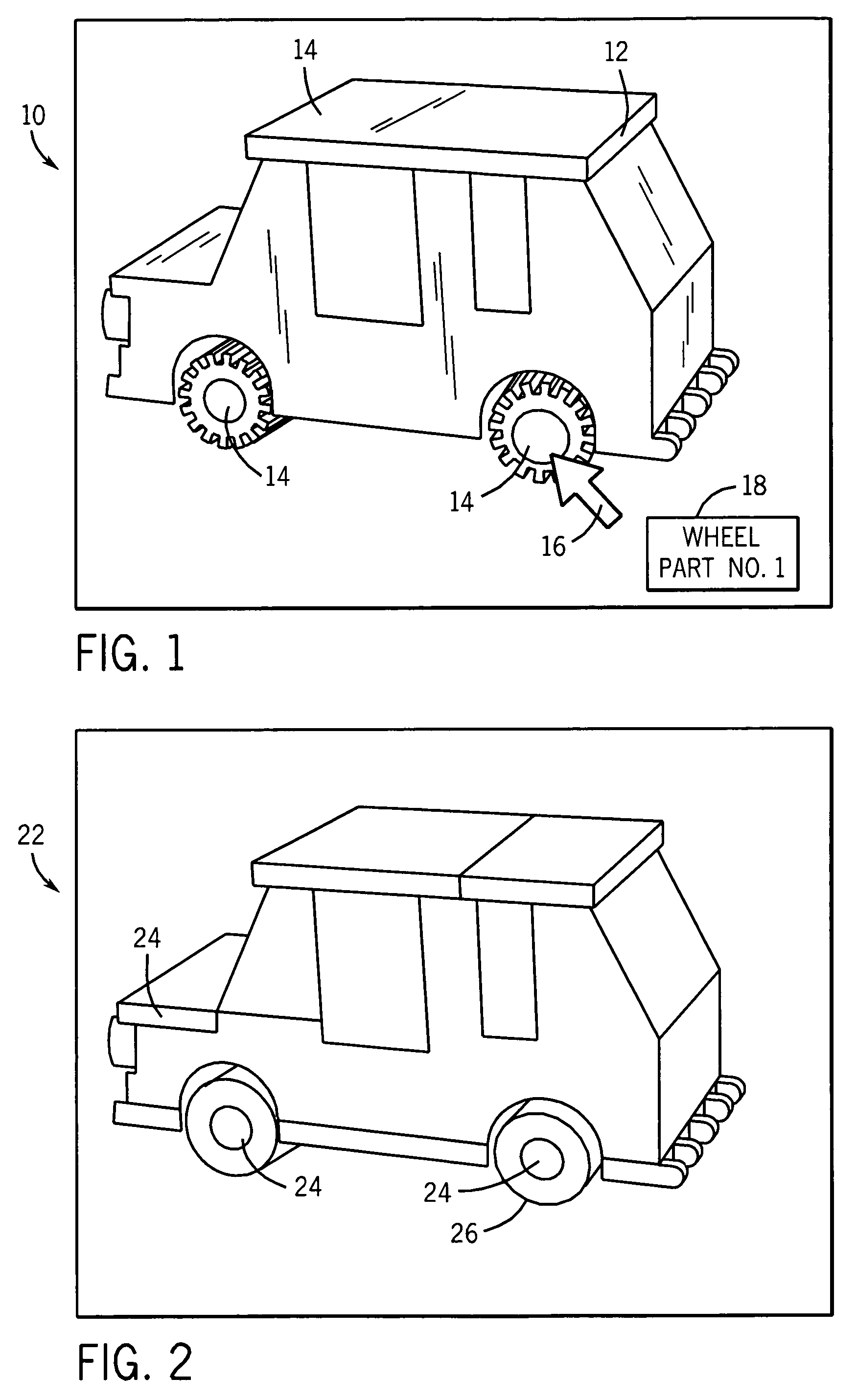
[0022] Turning now to the drawings and referring first to FIG. 1, an exemplary 2D image 10 is illustrated consisting of an assembly of image objects. In the illustrated example, the 2D image is of a toy car. Clearly, any suitable assembly of objects or even single objects can be analyzed and processed in accordance with the present invention. Moreover, it should be noted that the image presented in FIG. 1 is illustrated as it might appear on a computer screen. In general, the present invention facilitates analysis of digitized images to identify boundaries of image objects of interest. The view shown in FIG. 1, may, for example, be part of a digital catalog, manual, web tool, and so forth. The image will typically be stored in any conventional manner on a digital memory device and served to a user via a monitor. The image, where available as a web page, may be displayed in a conventional browser or other viewing application. Details of such browsers have been eliminated from the vie...


PUM


Abstract

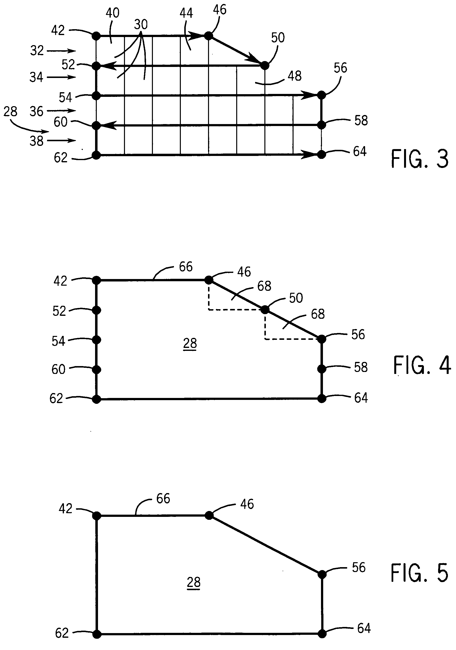
Image objects within two-dimensional images are identified by locating boundary points that describe line segments that define a polygon outlining each object. Processing follows lines of pixels between boundary points to determine whether additional pixels are a part of the same image object by reference to a discriminator, such as color. Boundary points are thus identified for contiguous pixels and contiguous lines. Arm-like regions are identified by recursive analysis in a similar manner. The resulting boundary point list may serve to identify the image object, such as for labeling or tagging in web-based manuals, catalogs, and so forth.

Description

BACKGROUND [0001] The present invention relates generally to the field of image rendering and image segmentation. More particularly, the invention relates to the identification of pixels in a digital image that are part of a desired grouping or item for identification of the grouping or item boundary. [0002] A range of applications exist for digital image rendering. In one set of applications, a two-dimensional (2D) image is displayed on a computer screen and specific items visible in the image are segmented for tagging in a display or web protocol. The tagging permits information relating to the items to be called up for display by a user. Such tagging may create so-called “hot links” to the related information on a part or assembly. Increasing interest exists in the field of information systems for such hot linking, particularly for catalogs, manuals, and so forth. However, many other applications exist for similar linking to related information relating to specific image items, s...

Claims


Application Information

Patent Timeline
IPC IPC(8): G06K9/48G06V10/46
CPCG06K9/4638G06K9/48G06T7/0083G06T2207/20136G06T7/12G06T7/181G06V10/457G06V10/46
Inventor BRUNO, JEANETTE MARIE
Owner GENERAL ELECTRIC CO
Learn More