Electric supply device for slide structure

a technology of electric supply device and slide structure, which is applied in the direction of electric device, coupling device connection, cable arrangement between relatively moving parts, etc., can solve the problems of increased operation force required to open the slide door b, worn guide rail, increased operation force required to move the slider, etc., to improve the reliability of electric supply to the slide structure, improve the durability of the portion of the wiring harness, and smoothly and securely carried out

Inactive Publication Date: 2007-05-17
YAZAKI CORP
View PDF3 Cites 2 Cited by
  • Summary
  • Abstract
  • Description
  • Claims
  • Application Information

AI Technical Summary

Benefits of technology

[0028] With the constitution described above, the bend restricting part greatly restricts the radius of bend of the portion of the wiring harness, thereby preventing the portion of the wiring harness from being bent largely when the slide structure is opened or closed. The bend restricting part is preferably a wall part or block part having a bent shape.
[0029] With the constitution described above, the portion of the wiring is harness is prevented from being bent with a small radius of bend, so that bending durability of the portion of the wiring harness is improved. The sliding action of the slider can be smoothly securely carried out, so that the reliability of the electric supply to the slide structure can be improved.

Problems solved by technology

However, in such a case, the slider 64 is affected by the downward pressing force due to the bending-counterforce of the wiring harness 68 and the sliding resistance of the slider 64 with respect to the guide rail is increased, thereby causing problems that the slider 64 and the guide rail are worn down due to the repeated opening and closing of the door and the sliding characteristic of the slider 64 is deteriorated especially when the slide door 62 is being opened, resulting in that the operation force required to open the slide door 62 is increased.
Moreover, for example, the electric wires are hardened when the temperature is low, causing the slider to be hardly moved, resulting in that the operation force required to move the slider is increased, that is, causing the deterioration in the opening-and-closing operation characteristic of the slide door 62.

Method used


Image

  • Electric supply device for slide structure
  • Electric supply device for slide structure
  • Electric supply device for slide structure

Examples


Embodiment Construction

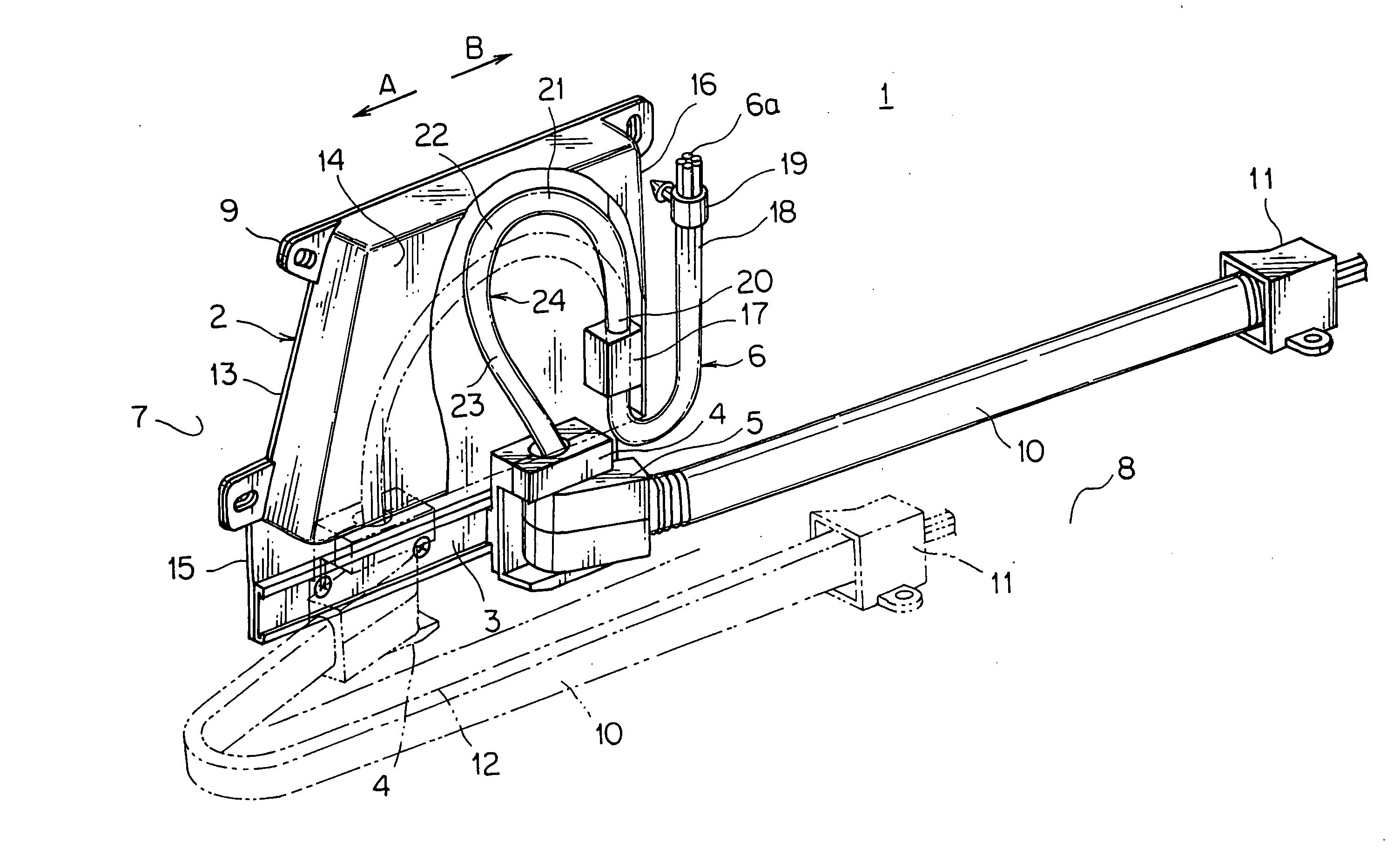
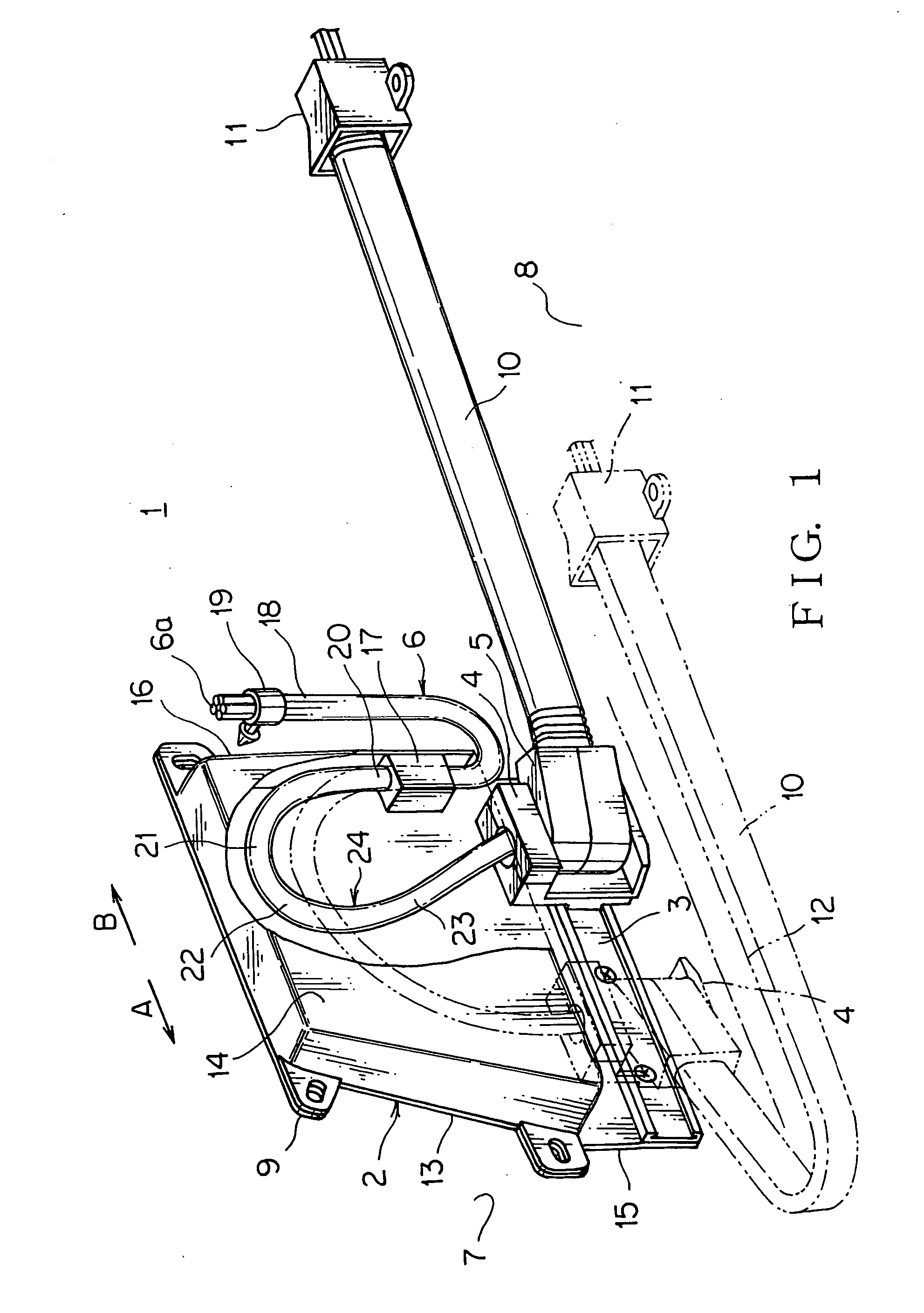
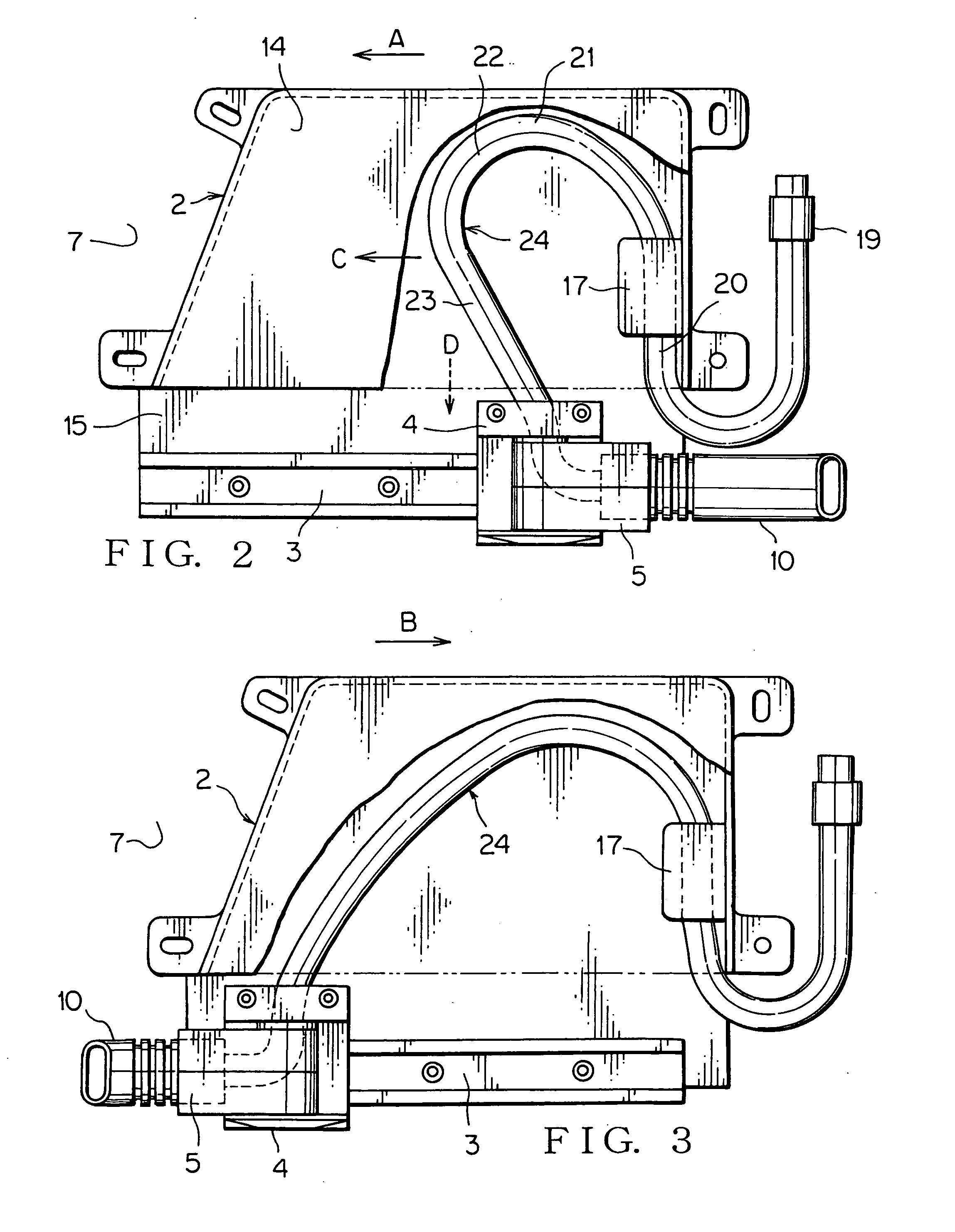
[0036]FIGS. 1-3 show a preferred embodiment of an electric supply device for a slide structure according to the present invention.

[0037] The electric supply device 1 for a slide structure includes: a rectangular case 2 made of synthetic resin; flat guide rail 3 made of metal provided at a lower part of the case 2; slider 4 made of synthetic resin slidably engaging with the guide rail 3; an oscillating member 5 provided to the slider 4, the oscillating member 5 being able to oscillate in the horizontal direction; and wiring harness 6 which is introduced into the case 2 upward from below, folded back in an arc-shape at an upper part of the case 2 and guided out to the outside passing through the slider 4 and the oscillating member 5.

[0038] In FIG. 1, the case 2 is fixed to a door inner panel made of metal of a slide door 7 situated on the right side of a vehicle with a bracket 9. A portion 10 of the wiring harness horizontally guided out to the outside from the oscillating member 5 ...


PUM


Abstract

The electric supply device for a slide structure includes: a guide rail provided on the side of the slide structure; and a slider slidably engaging with the guide rail, wherein a wiring harness is guided from the side of the slide structure to the side of a fixed structure through the slider, wherein a portion of the wiring harness on the side of the slide structure is raised up from a harness fixing part, folded back in a bent shape and introduced into the slider, so that the portion of the wiring harness effects bias force in a direction in which the slider slides.

Description

BACKGROUND OF THE INVENTION [0001] (1) Field of the Invention [0002] The present invention relates to an electric supply device for a slide structure, which device is mounted on the slide structure such as a slide door of a motor vehicle so as to supply electric power to an auxiliary machine of the slide structure. [0003] (2) Description of the Related Art [0004]FIG. 6 shows an example of a conventional electric supply device for a slide door (see Japanese Patent Application Laid-Open No. 2003-25850; FIG. 2). [0005] The conventional electric supply device 61 for slide door includes a laterally long case 63 provided to a slide door 62 situated on the left side of a motor vehicle, a slider 64 slidably engaging with a guide rail (not shown in the figure) in the case 63, an oscillating member 65 which is supported by a shaft perpendicular to the slider 64 and oscillates in the horizontal direction, and a caterpillar-shaped harness armored member 66 which is mounted being bent in a U-sha...

Claims


Application Information

Patent Timeline
Patent Type & Authority Applications(United States)
IPC IPC(8): H01R33/00
CPCB60R16/0215H02G11/00H02G11/006
Inventor NISHIJIMA, MASATAKAKISU, NAOMI
Owner YAZAKI CORP
Why Eureka
Try Eureka